27
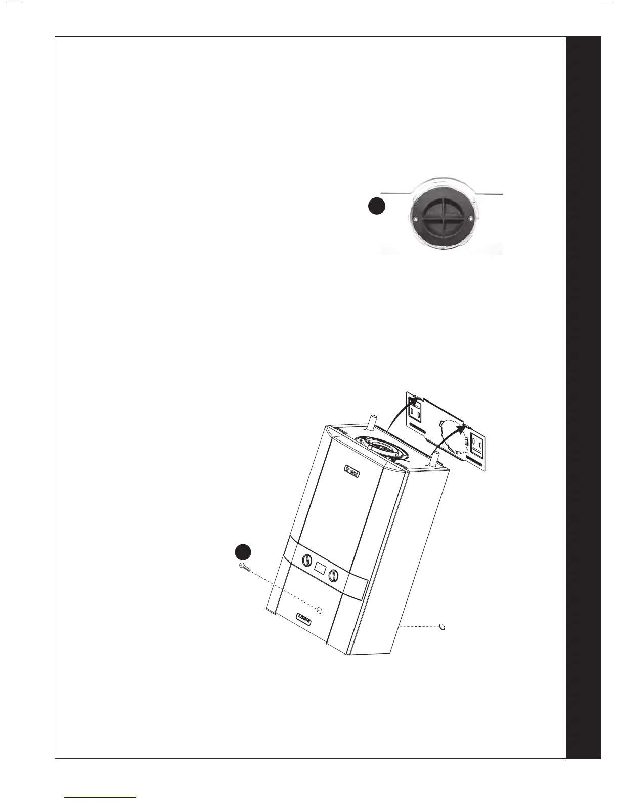
1. Remove the rear ue blanking disk.
2. Lift the boiler onto the wall plate, (refer to the
introduction section for safe handling advice),
ensuring the boiler is offered to the bracket tabs at
an angle as shown below, and carefully allow the
boiler to swing down to the wall as this movement
engages the rear ue air and ue seal.
3. Screw the boiler bottom retaining bracket to the
wall with the screw provided.
4. Remove the top ue blanking disk refer to
Frame 26. Fill the condensate trap within the
boiler by pouring a cupful of water into the ue
outlet. Take care to ensure that the water is only
poured into the ue outlet, and does not spill into
the boiler casing.
5. Replace the top ue blanking disc and retain with
the horseshoe bracket and xing screw previously
removed.
During assembly check that the ue seals do not
become dislodged.
 Loading...


