EasyManua.ls Logo

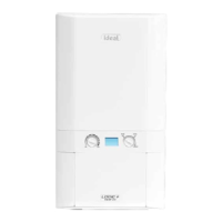
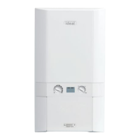
IDEAL Logic HEAT 24

IDEAL Logic HEAT 24
8 pages
To Next Page IconTo Next Page
Loading...
USERS GUIDE
LOGIC Heat
12, 15, 18, 24, 30
When replacing any part on this appliance, use only spare parts that you can be
assured conform to the safety and performance specification that we require.
Do not use reconditioned or copy parts that have not been clearly authorised by Ideal.
For installation guide see reverse of book
205862-2.indd 61 27/10/2010 14:43:08

Other manuals for IDEAL Logic HEAT 24

Question and Answer IconNeed help?

Do you have a question about the IDEAL Logic HEAT 24 and is the answer not in the manual?

IDEAL Logic HEAT 24 Specifications

General IconGeneral
BrandIDEAL
ModelLogic HEAT 24
CategoryBoiler
LanguageEnglish

Summary

Introduction

Safety

Electricity Supply

This appliance must be earthed. Supply: 230 V ~ 50 Hz. The fusing should be 3A.

Minimum Clearances

Required clearances for boiler casing for installation and servicing must be allowed.

Bottom Clearance

Bottom clearance after installation can be reduced to 5mm with an easily removable panel.

Boiler Reset Procedure

Boiler Controls and Operation

Control of Water Temperature

The boiler controls the central heating radiator temperature to a maximum of 80°C.

Frost Protection

Ensuring the boiler and system do not freeze during periods of absence.

Boiler Overheat Protection

The boiler will shut down in the event of overheating, displaying a fault code L-1.

Flame Failure

Indicates a fault code L-2 displayed when flame failure occurs.

Condensate Drain

The condensate drain must not be modified or blocked to prevent shutdown.

Troubleshooting

Operation Modes

Display codes indicating boiler status: standby, heating, or frost mode.

Fault Codes

Detailed list of fault codes, their descriptions, and recommended actions.
Related product manuals