EasyManuals Logo

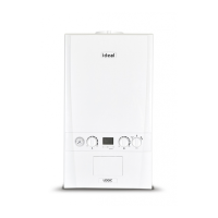
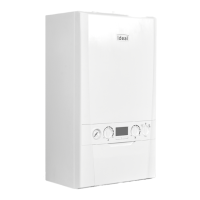
IDEAL LOGIC+ Combi 30 Installation And Servicing

IDEAL LOGIC+ Combi 30
72 pages
To Next Page IconTo Next Page
To Previous Page IconTo Previous Page
Page #34 background imageLoading...
Page #34 background image
34
INSTALLATION
Ideal Logic + Combi - Installation and Servicing
30
WIRING DIAGRAM
bk
p y
X13
123
bk
y
p
bk
y
p
Timer
r
b
bk
or
bk
1
X1A
X1BX1CX2X3
X5X6X8
23456123451234568 79
1234123456
X7
12345123456789
1011
Water
Flow
Turbine
p
bk
r
bk
Water
Pressure
Switch
PCB
Flow
Thermistor
Return
Thermistor
Earth
y/g
brb
bk
r
b br
y/g
Service
Connector
Selv Timer
- blue
- black
- brown
- red
- pink
- yellow
- white
- yellow/green
- grey
- orange
- violet
b
bk
br
r
p
y
w
y/g
g
or
v
KEY
Flame
Sensor
Electrode
Fan
bk
bk
b
y/g
br
y/g
y/g
Spark
Electrode
Spark
Generator
bk
Gas
Valve
b
bk
br
bk
b
v
Divertor
Valve
Pump
y/g
Frost
Stat
Main
Supply
Room
Stat
r v
bk
bk
v
g
bk
g
bk
b
b
y/g
br
br
bk
bk
bk
bk
r
r
r
r
b
b
r
bk
bk
Weather
Compensation
Opentherm
Room Stat
INSTALLATION

Other manuals for IDEAL LOGIC+ Combi 30

Questions and Answers:

Question and Answer IconNeed help?

Do you have a question about the IDEAL LOGIC+ Combi 30 and is the answer not in the manual?

IDEAL LOGIC+ Combi 30 Specifications

General IconGeneral
ModelLOGIC+ Combi 30
Boiler TypeCombi
Central Heating Output24.2 kW
Domestic Hot Water Output30.3 kW
Efficiency Rating94%
ErP RatingA
Flow Rate12.4 l/min
Dimensions700x395x278 mm
Fuel TypeNatural Gas
MountingWall Mounted
Warranty7 years
Central Heating Pressure3 Bar

Related product manuals