53
54
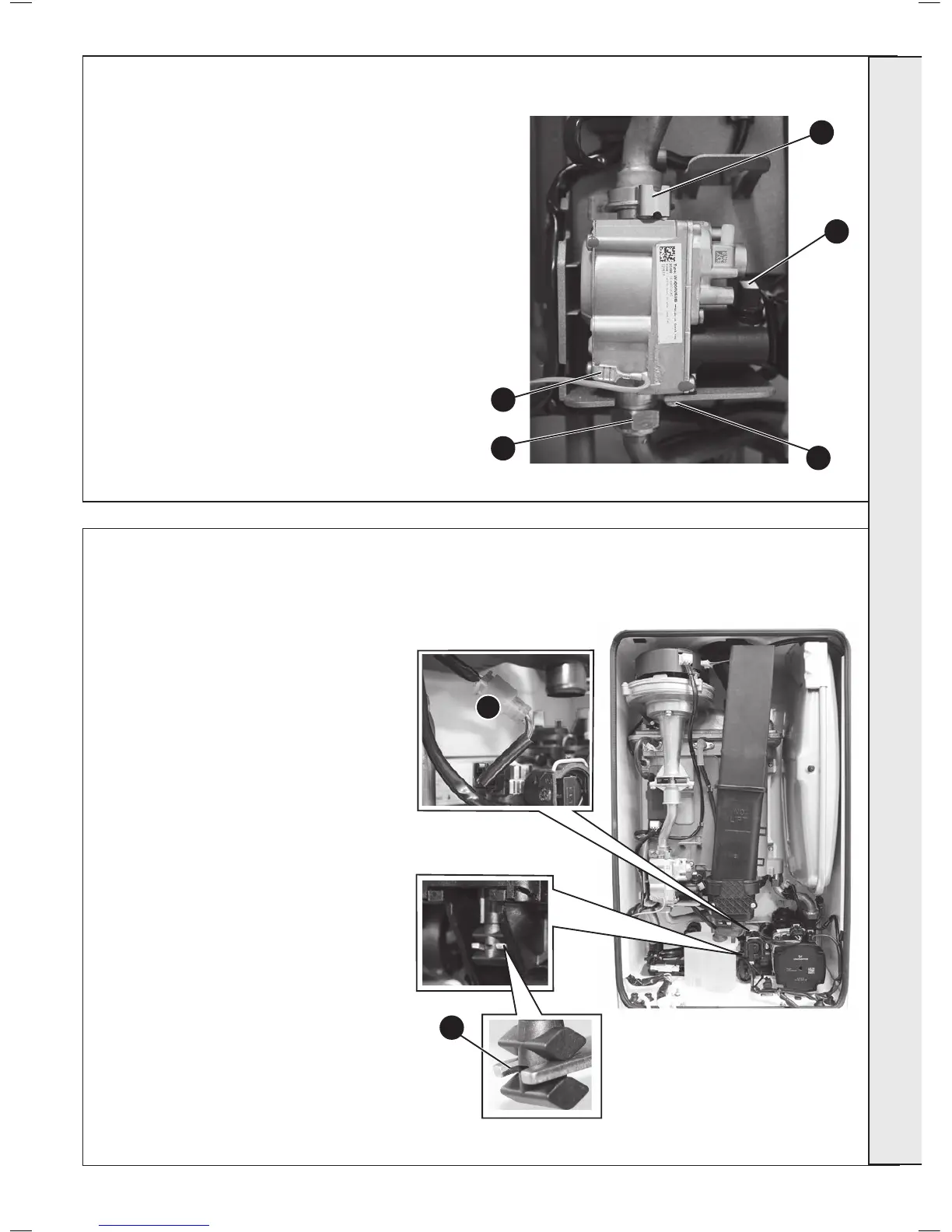
1. Refer to Frame 45.
2.
Unplug the electrical lead connection from the gas control valve.
3. Disconnect the earth wire.
4. Remove the outlet gas valve clip and slide the pipe upwards
5. Undo the gas inlet pipe union at the inlet to the gas valve.
6. Undo the single screw xing the gas valve to the mounting
bracket and withdraw the valve forwards.
7. Fit the new gas control valve ensuring that the O ring and
sealing washer are in place and reconnect gas and electrical
connections.
8. Check operation of the boiler. Refer to Frames 32-36.
3
5
6
4
2
To remove the motor:
1. Refer to Frame 45.
2. Remove the condensate trap/siphon. Refer to
Frame 42.
3. Disconnect the inline connector block.
4. Place a at bladed screwdriver in the actuator slot
provided and ease out the actuator.
5. Before replacing the diverter valve actuator
proceed as follows:
a. Re-connect the inline connector block.
b. Ensure that the switched live to the boiler is
off and that all DHW taps are shut and that
pre-heat is switched off.
c. Hold the mode knob in the restart position for
more than 10 secs.
d. Enter the Installer Mode (refer to Frame 34)
which moves the actuator into mid position.
e. The divertor valve will initially drive all the way
out, this may cause the spindle to become
detached from the body. If this occurs simply
screw back into the body so the cycle can
continue driving fully in before going to mid-
position.
f. Replace the actuator into the boiler.
6. Fit the new motor ensuring the arm is correctly
engaged in the metal fork and re-assemble in
reverse order ensuring the condensate trap/siphon
is relled with water.
7. Check the operation of the boiler. Refer to Frames
32-36.
Note. All spares will be delivered in mid-position
therefore ignore point 5 and proceed to point 6 after
re-connecting the inline connector.
3
6
 Loading...


