46
Installation and Servicing
Section 3 - Servicing
SERVICING
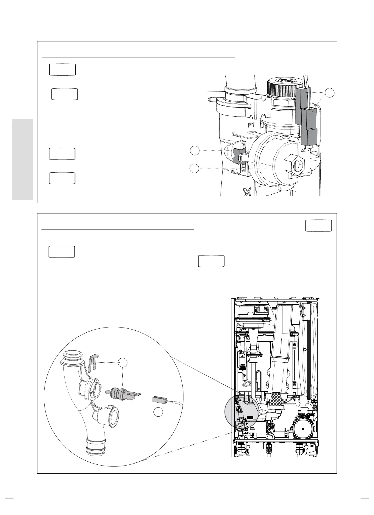
3.22 CH WATER PRESSURE SWITCH REPLACEMENT
1. Drain the boiler.
2. Pull o the two electrical connections.
3. Using a suitable tool, pull out the metal retaining clip.
4. Carefully withdraw the pressure switch.
5. Fit the new pressure switch and re-assemble in reverse
order. Ensure the ‘O’ ring is tted and replace clip.
6. Rell the boiler.
7. Check that the boiler operates..
Refer to Section
2.30 & 2.32
4
2
Refer to Section
3.2
Refer to Section
3.3
Refer to Section
2.17
3
Shown
rotated 90º
1. Drain down the boiler.
2. Unplug the electrical lead.
3. Remove the clip from the ow pipe and remove the
thermistor.
4. Fit the new thermistor, ensure ‘O’ ring is tted and replace
clip.
3.23 FLOW THERMISTOR REPLACEMENT
Refer to Section
3.3
Refer to Section
2.17
5. Reassemble.
6. Rell the boiler.
7. Check that the boiler operates.
2
3
Refer to Section
3.2