24
1
2
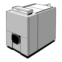
Fit the 2 rear attachment brackets (in the body accessories
pack) and attach them onto the framework using 2 bolts HM
12x25/25 + 4 washers L 12 and 2 nuts HM 12.
Caution: use the corresponding holes according to the
indications on the framework.
Put the lower insulation in place (fabric to top) packs IE 51 to
IE 57. Adapt length if necessary or bend the lower insulation
after the casing has been completely assembled.
8229-EN-11 A
Establish the location of the framework depending on the
direction in which the burner door will be opened and the
length of the burner.
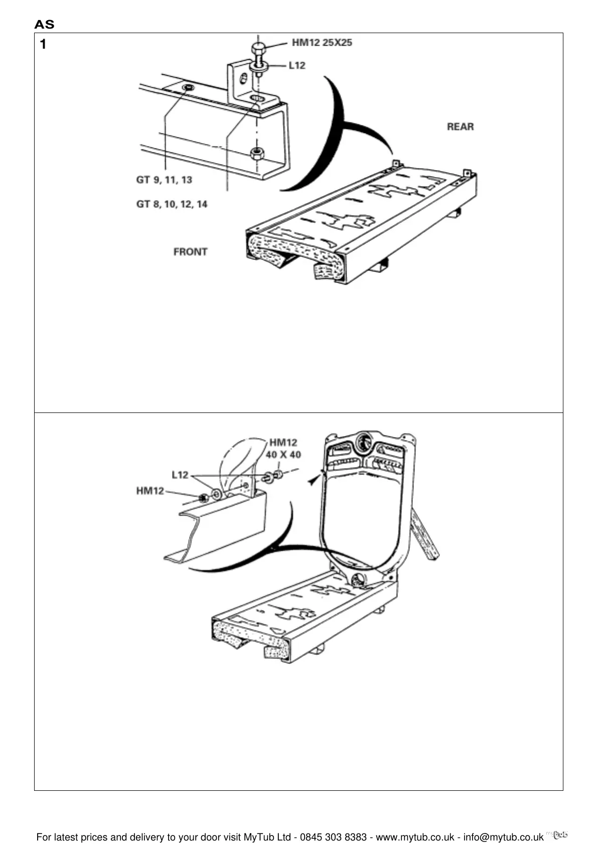
Put the rear section on the framework and support it. Attach
it at the brackets using 2 bolts HM 12x40/40 + 4 washers L
12 + 2 nuts HM 12.
Carefully put the thermocord in place (body accessories
pack) in the sealing groove.
Note: Do not pull on the cord when it is being put in, to
avoid stretching and to preserve its thickness.
8229-EN-12 A
Viceroy GT Range - Installation
ASSEMBLY
 Loading...


