28 Viceroy GT Range - Installation
ASSEMBLY
9
10
Using a pipe wrench, fit the 2 threaded rods (body accessory
pack) M 12x175 for the flue outlet.
Fix the outlet and return flanges (body accessories pack)
using 4 nuts H 19 for each flange (24mm spanner) and place
the gasket between them. For the GT 11 to 14 models, the
return flange is replaced by a flange with water balancing
tube.
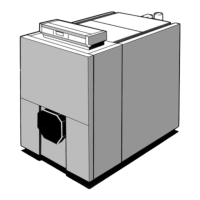
Fit the flue outlet onto the heating body (6 nuts H 12+6 flat
washers L 12-19mm spanner).
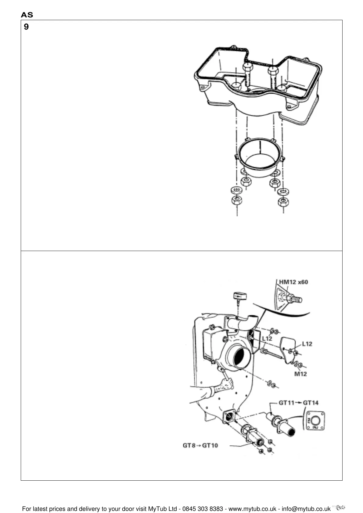
Fit 2 bolts HM 12x60 + 2 nuts on the flue outlet for the
cleaning traps (see detail).
Attach the cleaning traps (pack IE 20) using 4 bolts H 12 + 2
washers L 12 and 2 washers M 12.
Screw the flow rate controller on the sleeve. The direction of
the arrow on the casing must correspond to the direction of
the water flow in the pipework.
8229-EN-26 B
Fix the flue nozzle (body accessories pack) using the 4 bolts
HM 12x40 + 4 nuts H 12 and 4 washers on the flue outlet
(pack CS 20)
8229-EN-25 B
 Loading...


