30
13
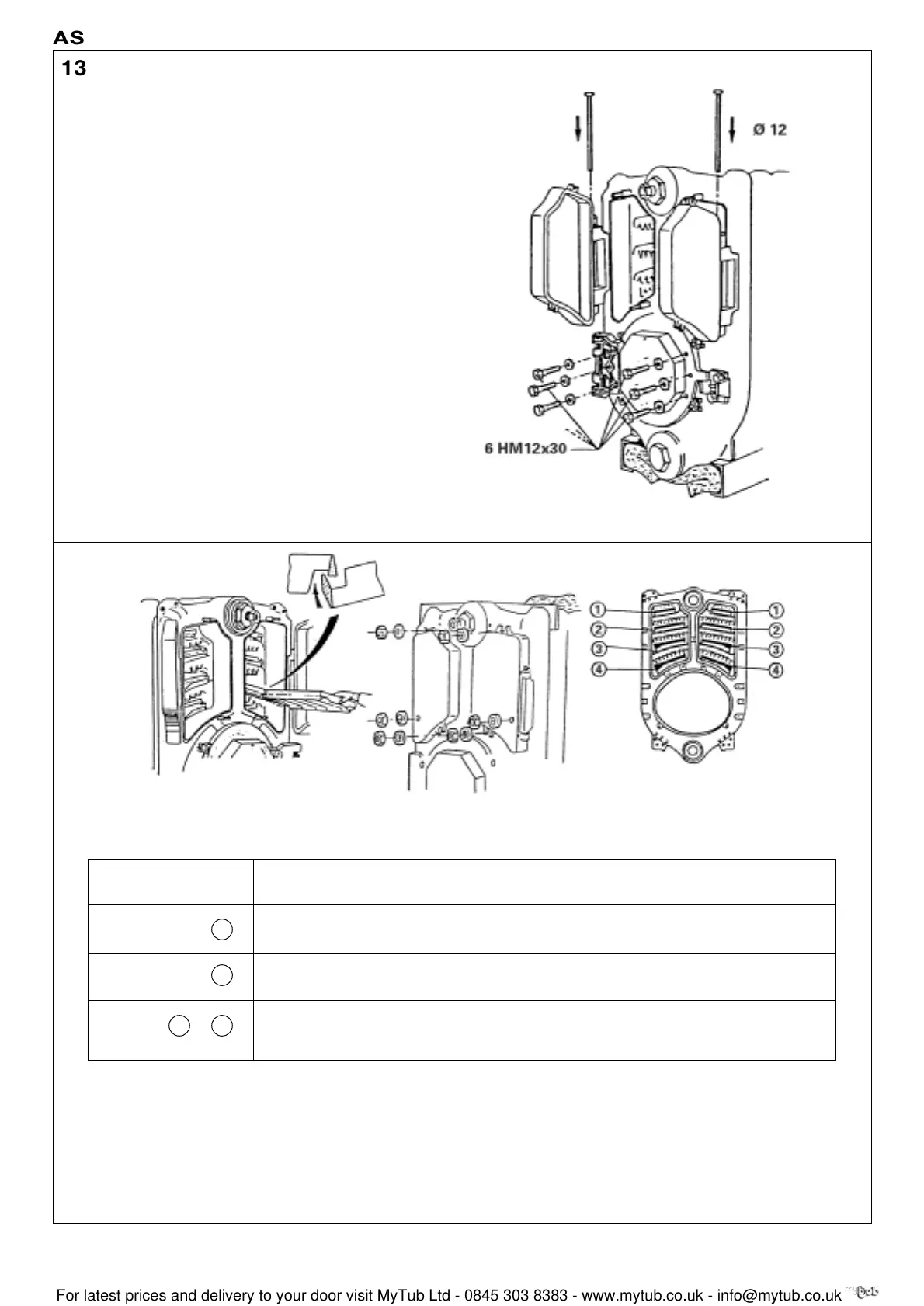
Fit the hinge (body accessories pack) on the burner door using
the 3 bolts HM 12x30 + 3 washers L 12 (previously removed).
Leave the 3 bolts HM 12x30 + 3 washers L 12 on the burner
door in place on the opposite side to the hinge.
Fit the left and right hand sweeping doors in place with their
pin (pack IE 20).
8229-EN-21 A
Remark: The part number of the baffles is marked on the
casting.
Install the upper (1), middle (2) and lower (3) + (4) baffles,
respecting the sequence of assembly given in the chart.
Important: Interlock the baffles one into another before
placing them in the flue way.
Close the cleaning doors and fix with 3 HM12 nuts + 3 L12
washers. After the body assembly, the installer must test the
pressure at a equal to 1.5 x the service pressure.
8229-EN-22 8229-EN-51
8229-EN-28
Viceroy GT Range - Installation
ASSEMBLY
14
Baffles (by flue way) Viceroy GT 8 Viceroy GT 9-10 Viceroy GT 11-12 Viceroy GT 13-14
pack CS30 pack CS31 pack CS32 pack CS33
Upper 8229-0010 2x8229-0010
then 2x then 3x
8229-0022 8229-0010 1x8229-0022 8229-0010
Middle 8229-0011 2x8229-0011
then 2x then 3x
8229-0023 8229-0011 1x8229-0023 8229-0011
Lower 8229-0012 2x8229-0012
then 2x then 3x
8229-0024 8229-0012 1x8229-0024 8229-0012
1
2
43+
 Loading...


