33
22 23
Screw the control panel at the front on the top panel using 2
self tapping screws dia. 3.94x12.7 + lock washers.
Carefully unwind and remove the various bulbs of the control
panel by passing them through the orifice of the front top
cover. Insert them into the small pocket and maintain them
there using a spring.
Fix the control panel at the rear, on the top panel using 2 self
tapping screws dia. 3.94x25 + lock washers.
Carefully unwind and remove the various bulbs of the control
panel by passing them through the orifice of the front top
cover. Insert them into the small pocket and maintain them
there using a spring.
8229-EN-33 A
Electrical connections
Make the electrical connections on the two terminal blocks
provided for this purpose inside the control panel
See chapter 7 of the instructions for the Standard and E
control panels or the instructions particular to the DIEMATIC
control panel. Close the control panel (2 self tapping screws
+ lock washers).
8229-EN-34 A
Position the front side panels (length 520) in the lower casing
supports, then attach them in the wiring ducts.
Fix at the front onto the lower casing supports using 2 bolts
HM 5x12 + lock washers and at the front top panel using 2
screws dia. 3.94x12.7 + lock washers.
8229-EN-35 A
Standard control panelDeluxe control panel
20 21
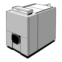
Viceroy GT Range - Installation
ASSEMBLY
 Loading...


