1: GENERAL INFORMATION
1-6 « FC4A MICROSMART USER’S MANUAL »
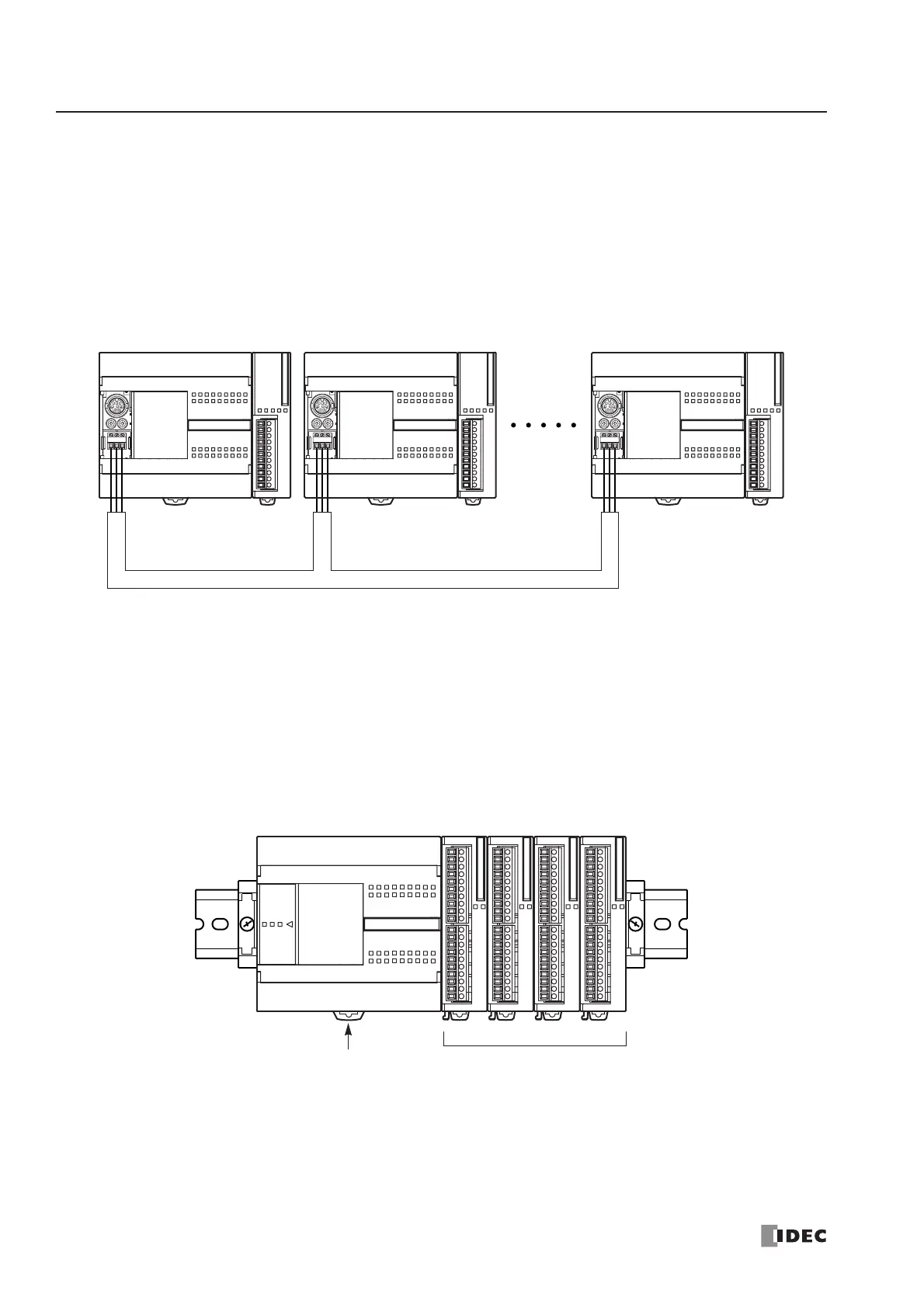
Data Link System
With an optional RS485 communication adapter installed on the port 2 connector, one 16- or 24-I/O type CPU module at
the master station can communicate with 31 slave stations through the RS485 line to exchange data and perform distrib-
uted control effectively. The RS485 terminals are connected with each other using a 2-core twisted pair cable.
The same data link system can also be set up using any slim type CPU modules mounted with RS485 communication
modules.
For details about the data link communication, see page 25-1.
Basic System
The all-in-one 10-I/O type CPU module has 6 input terminals and 4 output terminals. The 16-I/O type CPU module has 9
input terminals and 7 output terminals. The 24-I/O type CPU module has 14 input terminals and 10 output terminals. Only
the 24-I/O type CPU module has an expansion connector to connect I/O modules. When four 16-point input or output
modules are connected to the 24-I/O type CPU module, the I/O points can be expanded to a maximum of 88 points.
Any slim type CPU module can add a maximum of seven expansion I/O modules.