Engineering
38
HR9Z-B2192 8/2020
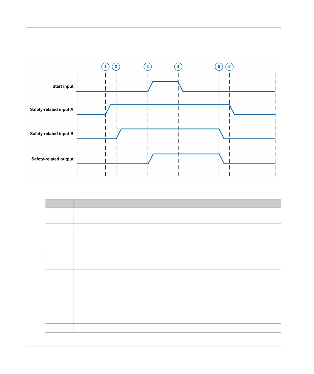
Timing Diagram for Example with Emergency Stop
The following timing diagram provides an overview of the example with Emergency Stop.
Legend
Item Description
1
The first safety-related input (A) is activated (actuator of Emergency Stop button pulled out).
The device remains in the defined safe state.
2
The second safety-related input (B) is activated (second output contact of Emergency Stop
button).
If an application function with synchronization
(see page 42)
is used, the first safety-related
output (A) is only activated if the second safety-related input (B) is activated within the
synchronization time.
The start button has not yet been pressed so the start condition is not yet fulfilled and the
device remains in the defined safe state.
3
The start button is pressed.
The start condition is fulfilled. See the chapter Start Functions
(see page 65)
for detailed
information on the start functions.
The safety-related output is activated within the activation delay time
(see page 29)
.
If an application function with synchronization
(see page 42)
of two input channels is used,
the safety-related output is only activated if the two channels of the safety-related input have
been activated within the synchronization time.
The motor runs. The device is not in the defined safe state.
4
The start button is released.