Installation
52
HR9Z-B2192 8/2020
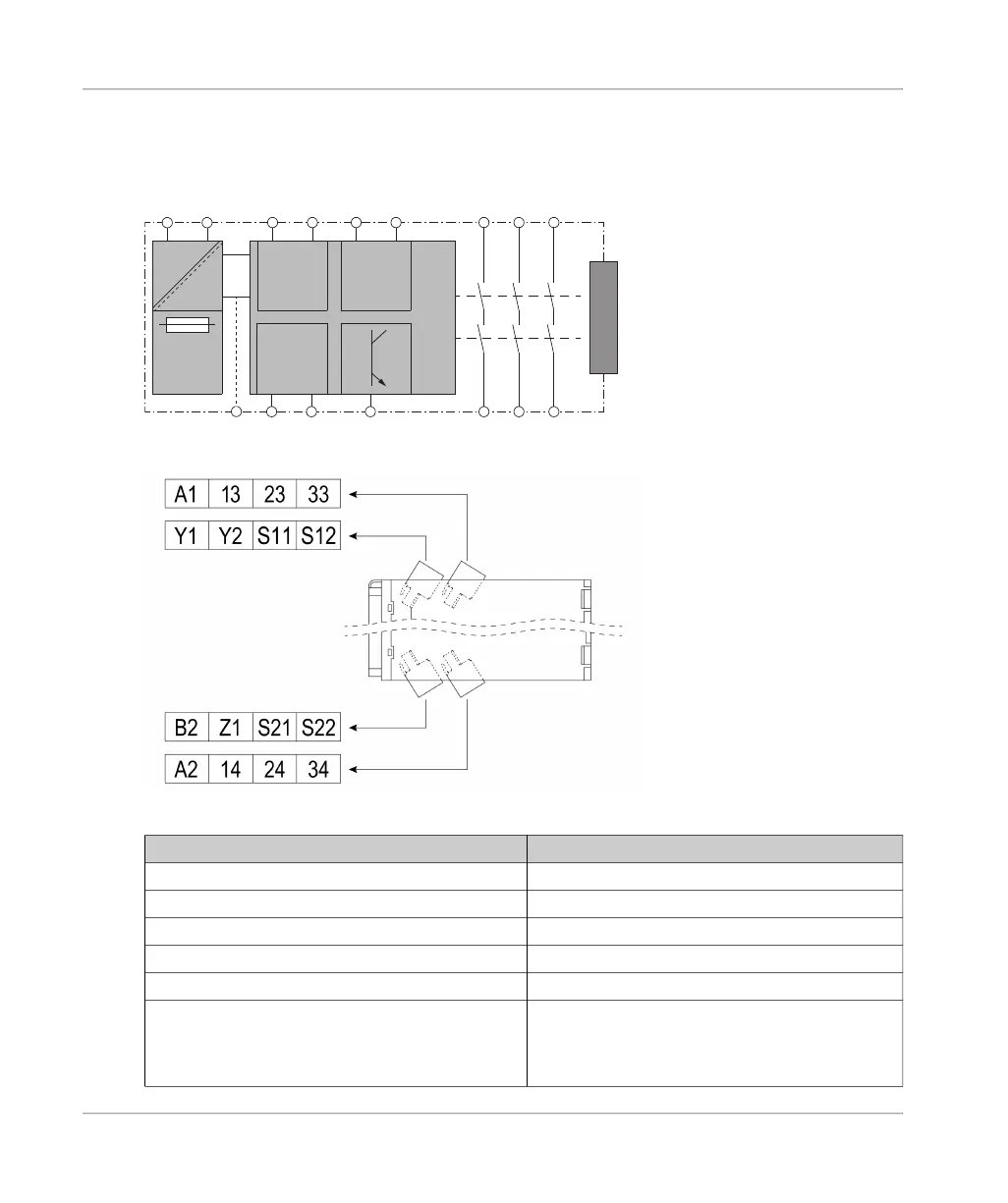
Block Diagram and Terminals
The following drawings present the block diagram and the terminals with their designations in the
removable terminal blocks.
Terminal Designation Explanation
A1, A2 Power supply
Y1 Control output (DC+) of start input
Y2 Input channel (CH+) of start input
S11, S21 Control outputs (DC+) of safety-related inputs
S12, S22 Input channels (CH+) of safety-related inputs
B2 Terminal for common reference potential for 24 VDC
signals. The power supplies of the connected
equipment must have a common reference potential
to be connected to this terminal.
AC/DC
DC
DC+ CH+
Input
DC+ CH+
Start
DC+ CH+
Input
K1
K2
Power
Supply
A1 A2 S11 S12 Y1 Y2
S21 S22 Z1B2
13
14
23
24
33
34
EXT