FC6A S
ERIES
MICROS
MART
L
ADDER
P
ROGRAMMING
M
ANUAL
FC9Y-B1726 18-3
18: P
ULSE
O
UTPUT
I
NSTRUCTIONS
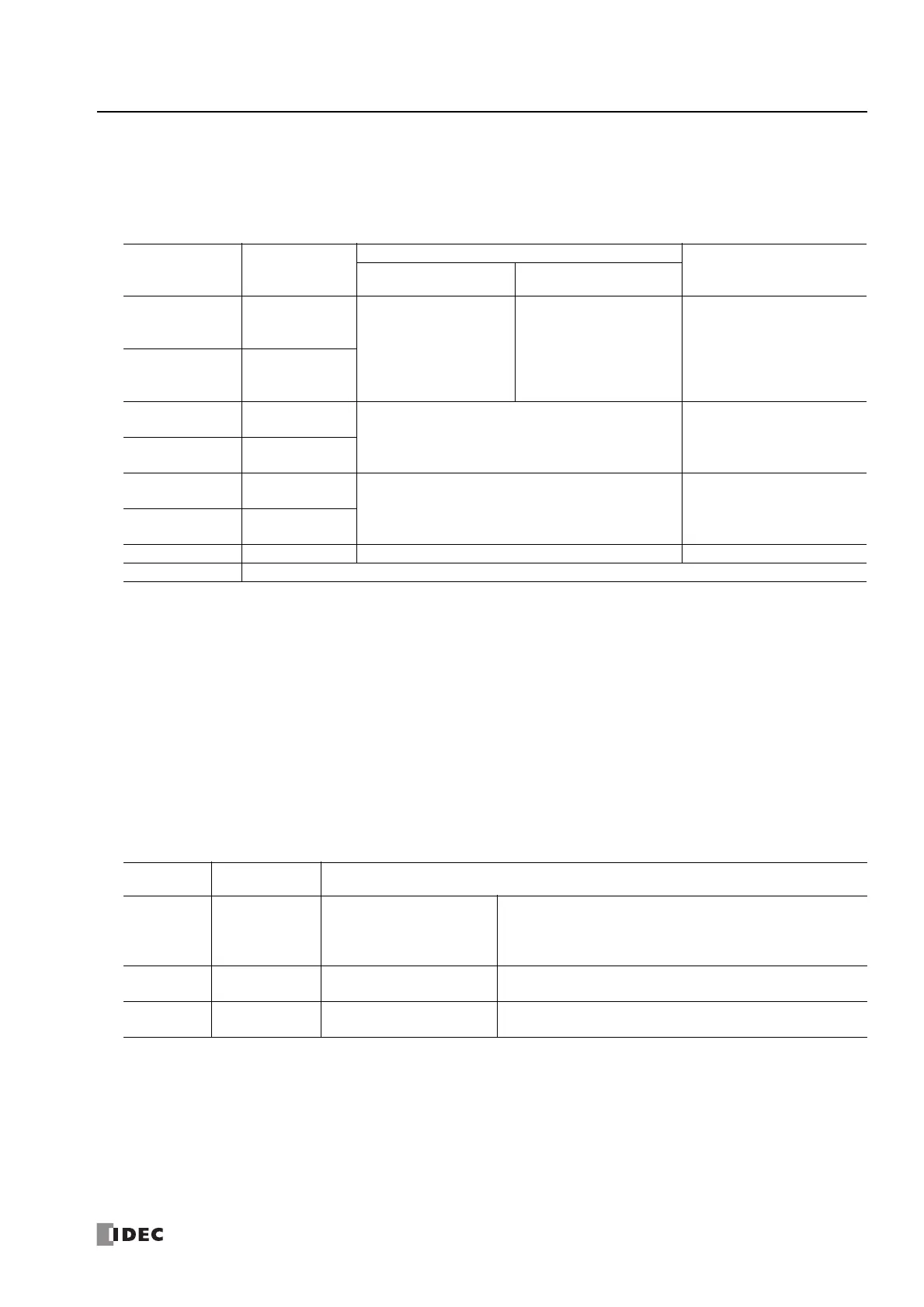
3. S1 (source 1): Control register
S1 specifies the first data register of the data registers to use with PULS1, PULS2, PULS3, or PULS4 instructions.
Starting from the specified data register, 8 consecutive data registers are used.
Specify the first data register so that the device range is not exceeded.
The operation mode and pulse frequency settings differ by the CPU module type and the instruction.
*1 The upper and lower data registers change according to the 32-bit data storage method specified.
For details, see "32-bit Data Storage" on page 3-9.
4. S2 (source 2): Initialization Input
S2 specifies the initialization input. When the initialization input is turned on, the initial values configured in the WindLDR PULS
dialog box, on the Settings tab, are stored in the control registers. An external input or an internal relay can be specified.
When the initialization input is on, the initial values are written to the data registers with each scan. (Even when the PULS
instruction is not executed (when not on), if the initialization input is turned on, the initial values are stored in the data
registers.) To only initialize the values one time, use the initialization input in combination with the SOTU (single output up)
instruction or the SOTD (single output down) instruction.
5. D1 (destination 1): Operation Status
D1 specifies the first internal relay of the internal relays that store the operation status.
Starting from the specified internal relay, 3 sequential internal relays are used.
Specify the first internal relay so that the device range is not exceeded.
Storage
destination
Function
Setting
Reference
All-in-One CPU Module
CAN J1939 All-in-One CPU
Module/Plus CPU Module
Starting number+0
Output pulse
frequency
(high word)
*1
PULS1, PULS2:
15 to 100,000
(increments of 1 Hz)
PULS3, PULS4:
15 to 5,000
(increments of 1 Hz)
PULS1 to PULS4:
15 to 100,000
(increments of 1 Hz)
"6. Output pulse frequency" on
page 18-4
Starting number+1
Output pulse
frequency
(low word)
*1
Starting number+2
Preset value
(high word)
*1
1 to 100,000,000 pulses "8. Preset value" on page 18-4
Starting number+3
Preset value
(low word)
*1
Starting number+4
Current value
(high word)
*1
1 to 100,000,000 pulses "9. Current value" on page 18-4
Starting number+5
Current value
(low word)
*1
Starting number+6 Error status 0 to 4 "10. Error status" on page 18-4
Starting number+7 Reserved
Storage
Destination
Function Setting
Starting
number+0
Pulse output ON
0: Pulse output OFF
1: Pulse output ON
This relay turns on during pulse output.
This relay turns off when pulse output stops.
This relay turns off when the specified number of pulses are output
and output ends.
Starting
number+1
Pulse output
complete
0: Pulse output not complete
1: Pulse output complete
This relay turns on when pulse output is complete.
This relay turns off when pulse output starts.
Starting
number+2
Overflow
0: None
1: An overflow has occurred
When pulse counting is enabled, this relay turns on when a pulse is
output that exceeds the configured preset value.
 Loading...
