FC6A S
ERIES
MICROS
MART
L
ADDER
P
ROGRAMMING
M
ANUAL
FC9Y-B1726 18-37
18: P
ULSE
O
UTPUT
I
NSTRUCTIONS
Start monitoring the origin signal with the fall in the proximity signal
Notes:
• If a pulse output instruction is simultaneously executed with the same output, a user program execution error will occur. Error code 48 will be
stored in D8006 and instructions that are executed later will be canceled.
• The ZRN instruction cannot be used in an interrupt program. If used in an interrupt program, a user program execution error will occur.
Error code 18 will be stored in D8006 and instruction execution will be canceled.
• If a pulse output instruction is executed with the relay output type, a user program execution error will occur. Error code 19 will be stored in
D8006 and instruction execution will be canceled.
• For details about the user program execution errors, see "User Program Execution Errors" on page 3-10.
Valid Devices
*1 Special data registers cannot be used.
*2 Special internal relays cannot be used. Only 0 can be specified as the first digit of the internal relay number. 1 to 7 cannot be specified.
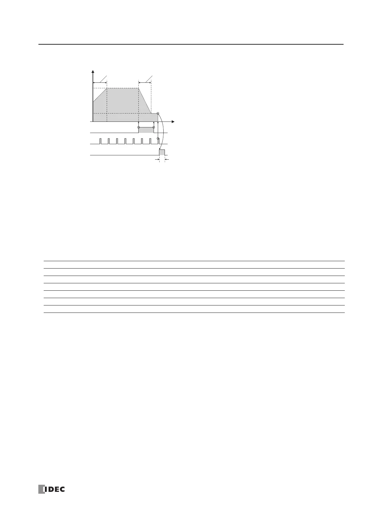
(1)
The rise in the proximity signal is detected and the frequency
starts being decreased.
(2)
The fall in the proximity signal is detected and the origin signal
starts being monitored.
(3)
The rise in the origin signal is detected and pulse output is
stopped.
(4)
When pulse output stops, the complete signal turns on at the
same time.
(5)
The on period for the complete signal is one scan or longer but
less than two scans.
ON
OFF
ON
OFF
ON
OFF
(1)
(3)
(4)
(5)
(2)
One scan or longer but less than two scans
Frequency
increase time
Steady pulse frequency
Creep pulse frequency
Initial pulse frequency
S3: Proximity signal
S4:
Origin signal
ON
OFF
ON
OFF
D2: Complete signal
ON
OFF
Frequency
decrease time
[t]
[Hz]
Device Function I Q M R T C D P Constant Repeat
S1 (Source 1) Control register ——————X
*1
—— —
S2 (Source 2) Initialization input X — X — — — — — — —
S3 (Source 3) Proximity signal X—X————— — —
S4 (Source 4) Origin signal X—X————— — —
D1 (Destination 1) Operation status — — X
*2
————— — —
D2 (Destination 2) Complete signal — X X
*2
————— — —
 Loading...
