FC6A S
ERIES
MICROS
MART
L
ADDER
P
ROGRAMMING
M
ANUAL
FC9Y-B1726 19-31
19: PID C
ONTROL
I
NSTRUCTION
9. Output Manipulated Variable (MV) (S1+16, S1+17)
If the Analog Value check box is selected, select Analog Output or Data Register to output the analog value.
If the Analog Value check box is cleared, the analog value is not output.
If the Digital Value check box is selected, Control Output (S3+14) turns on and off.
If the Digital Value check box is cleared, Control Output (S3+14) does not turn on and off.
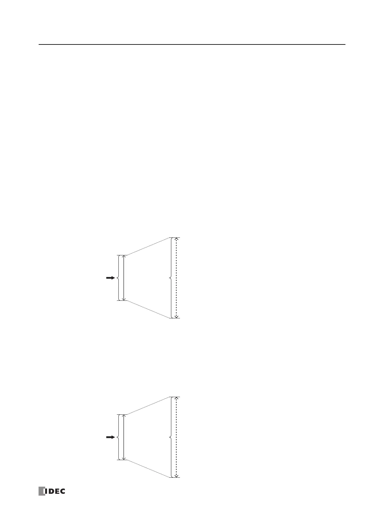
When Analog Output is specified
An analog output of an analog I/O cartridge or analog I/O module can be selected. Specify the analog output with the node,
module, and analog output number.
• For auto mode, Output Manipulated Variable (S1+16, S1+17) is converted to the full scale in the range of the minimum value and
maximum value of the analog output and output from the specified analog output number.
• For manual mode, Manual Mode Output MV (S1+14, S1+15) is converted to the full scale in the range of the minimum value and
maximum value of the analog output and output from the specified analog output number.
The analog output value converted to the full scale can also be checked with Output Manipulated Variable (Analog Value)
(S1+66, S1+67).
For switching between auto/manual mode, see "S3: Control Relay" on page 19-37.
Note: To use an analog output, the analog output must be configured in advance.
For details on analog output settings, see Chapter 9 "Analog I/O Modules" in the "FC6A Series MICROSmart User’s Manual".
When Data Register is specified
• For auto mode, the value of Output Manipulated Variable (MV) (S1+16, S1+17) converted to the full scale in the range of the
minimum value and maximum value is stored in Output Manipulated Variable (MV) Analog Value (S1+66, S1+67).
• For manual mode, the value of Manual Mode Output MV (S1+14, S1+15) converted to the full scale in the range of the minimum
value and maximum value is stored in Output Manipulated Variable (MV) Analog Value (S1+66, S1+67).
For switching between auto/manual mode, see "S3: Control Relay" on page 19-37.
Node: Select the node of the module having the analog output to specify.
Node 0:
Plus CPU module/Expansion interface remote master module
Node 1 to 10:
Expansion interface remote slave module
Module: Select the module having the analog output to specify.
CPU/HMI Module: Analog I/O cartridge
Expansion Module 1 to 15: Analog I/O module
Analog Input No.: Select the analog output number from AO0 to AO7.
Minimum Value
Output Manipulated
Variable (MV)
(S1+16, S1+17)
Full Scale of
Analog output
MV High Limit
(S1+32, S1+33)
MV Low Limit
(S1+30, S1+31)
Maximum Value
Minimum Value
Output Manipulated
Variable (MV)
(S1+16, S1+17)
Full Scale of Output
Manipulated Variable
(MV) Analog Value
MV High Limit
(S1+32, S1+33)
MV Low Limit
(S1+30, S1+31)
Maximum Value
 Loading...
