BIBD-ICP User’s Manual
Chapter 2: Hardware installation
2.1 Central Processing Unit (CPU)
The mainboard includes an onboard Intel® SOC, and a cooler has been installed to
provide sufficient cooling.
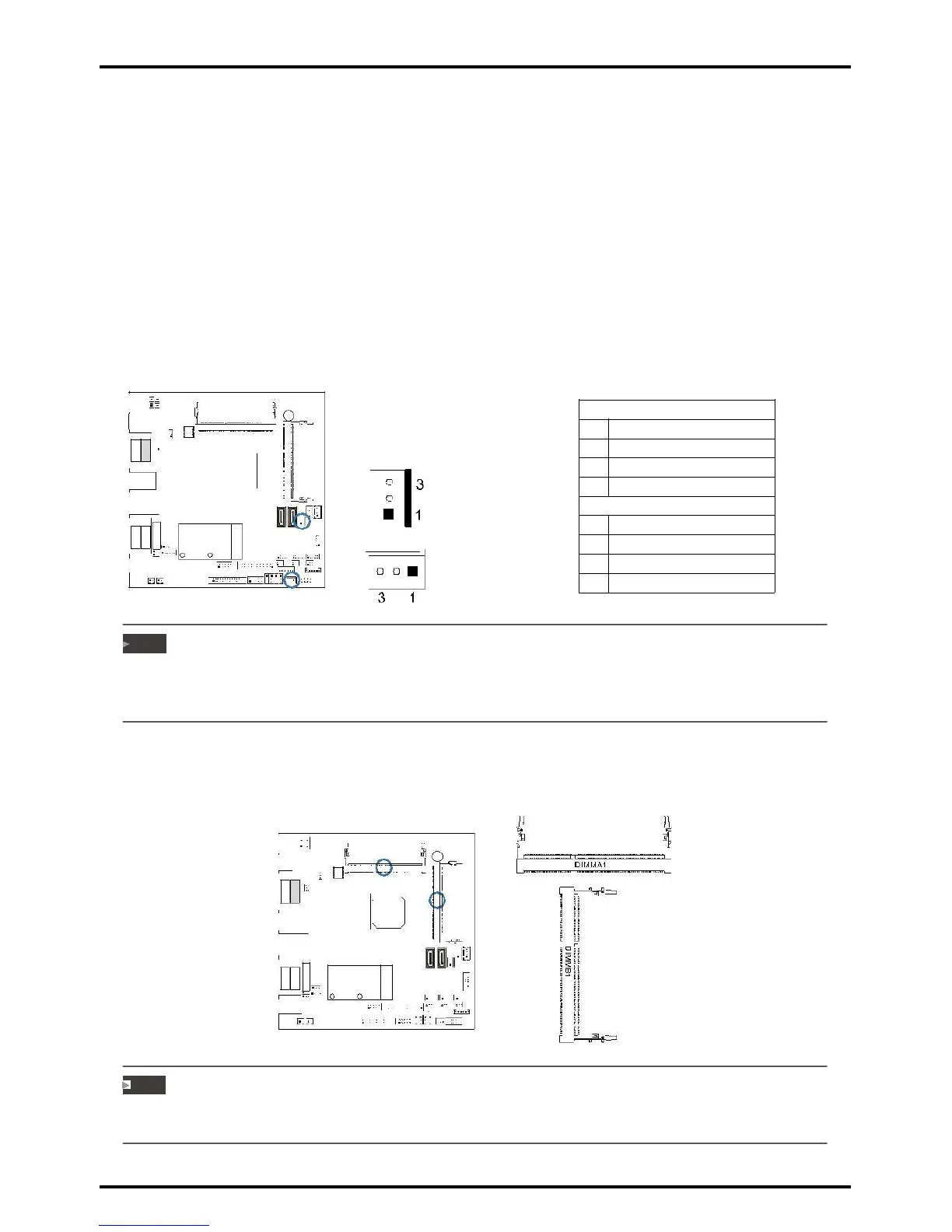
2.2 Connect Cooling Fans
These fan headers support cooling-fans built in the computer. The fan cable and connector
may be different according to the fan manufacturer. Connect the fan cable to the
connector while matching the black wire to pin#1.
CPU_FAN1: CPU fan header
SYS_FAN1: System fan header
JCFAN1
»»» System Fan Headers support 3-pin head connectors. When connecting with wires onto connectors,
please note that the red wire is the positive and should be connected to pin#2, and the black wire is
Ground and should be connected to GND.
2.3 Installing System Memory
DIMMA1/B1: DDR3L Memory Module (204pin SO-DIMM)
Note
»»» The DIMM must be installed to DIMMA1 slot first. The DIMMB1 slot is optional.
»»» If the DIMM does not go in smoothly, do not force it. Pull it all the way out and try again.
Chapter 2: Hardware installation | 9