BIBD-ICP User’s Manual
2.5 Jumpers / Headers / Connectors
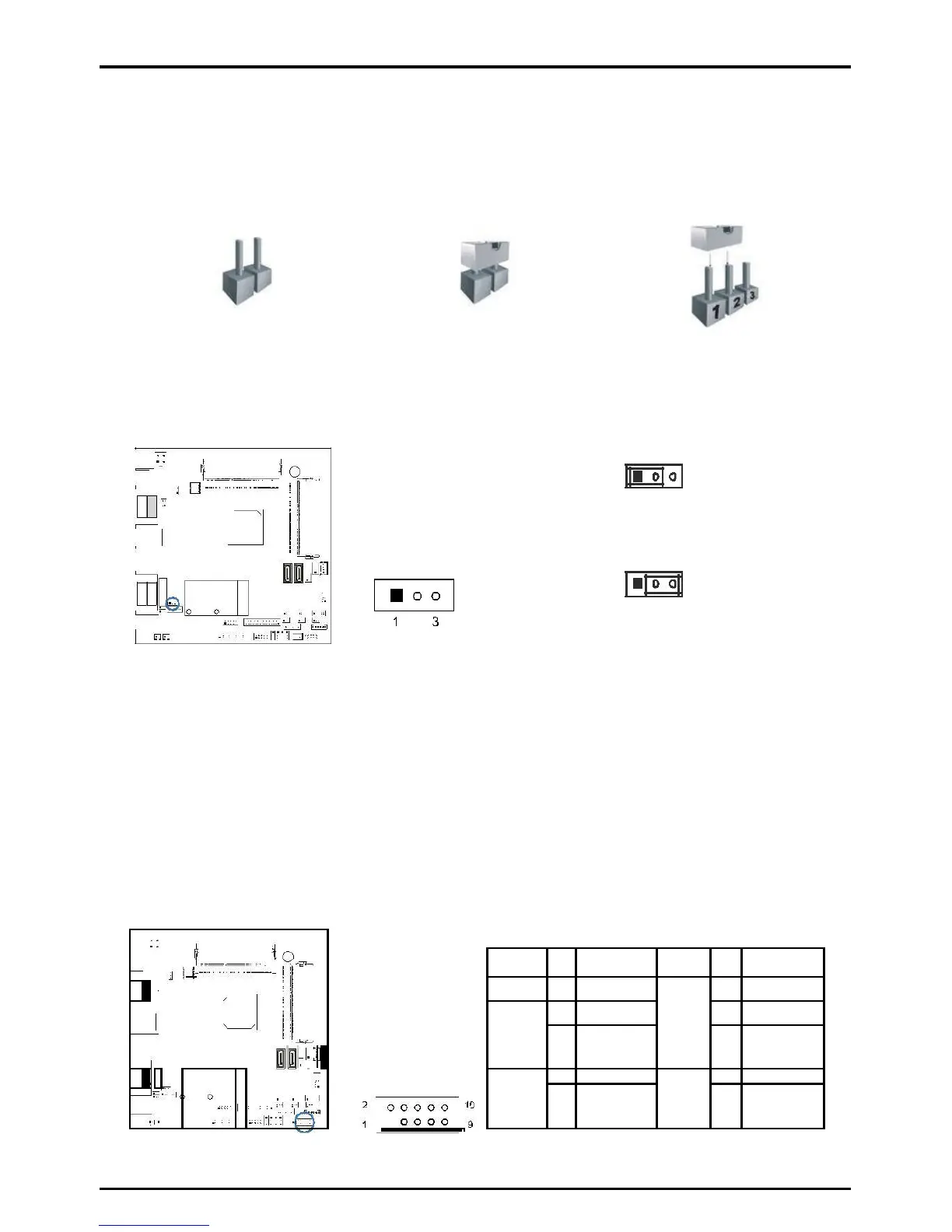
Jumper Setting
The illustration shows how to set up jumpers. When the jumper cap is placed on pins,
the jumper is “close”, if not, that means the jumper is “open”.
Pin opened Pin closed Pin 1-2 closed
JCMOS1: Clear CMOS Jumper
Placing the jumper on pin2-3 allows user to restore the BIOS safe setting and the CMOS data.
Please carefully follow the procedures to avoid damaging the motherboard.
1 3
Pin 1-2 Close: Normal Operation (Default)
1 3
Pin 2-3 Close: Clear CMOS data
Clear CMOS Procedures:
1. Remove AC power line.
2. Set the jumper to “Pin 2-3 close”.
3. Wait for five seconds.
4. Set the jumper to “Pin 1-2 close”.
5. Power on the AC.
6. Reset your desired password or clear the CMOS data.
JPANEL1: Front Panel Header
This 10-pin header includes Power-on, Reset, HDD LED, and Power LED connection. It
allows user to connect the system case’s front panel switch functions.