14
※ iTDC Quick Installation Guide
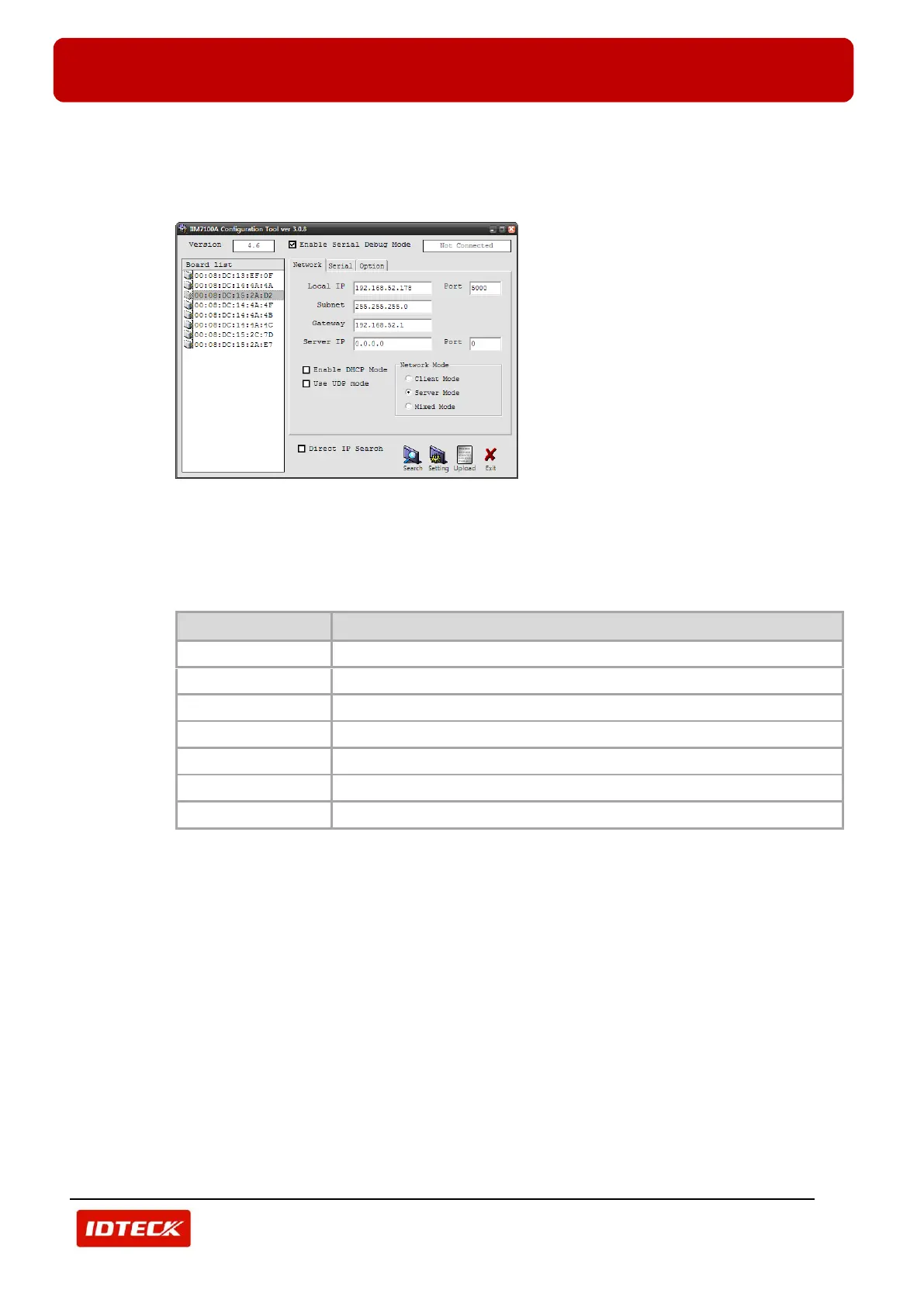
In the ‘Board List’, MAC address of TCP /IP Module is displayed.
4) Check MAC address of TCP/IP Module (described on TCP/IP module) and then select it. Setting
information is displayed as below.
5) Select ‘Network’ tab.
Input network information of selected TCP/IP module to ‘Local IP’, ‘Subnet’, and ‘Gateway’.
Network information can be assigned from network manager.
Input ‘5000’ for ‘Port’, ‘0.0.0.0’ for ‘Server IP’(default), ‘0’ for ‘Server IP Port’. Select ‘Server Mode’ for
‘Network Mode’. Refer to table below.
The IP address assigned from corresponding network (Not duplicated)
The Gateway assigned from corresponding network (Not duplicated)
The Subnet Mask assigned from corresponding network (Not duplicated)
6) Select ‘Serial’ tab.
Select serial communication setting value (‘Speed’, ‘Data Bit’, ‘Parity’, ‘Stop Bit’, ‘Flow’) of selected
TCP/IP module.
Select ‘9600’ for ‘Speed’, ‘8’ for ‘Data Bit’, ‘None’ for ‘Parity’ ‘1’ for ‘Stop Bit’ ‘CTS/RTS’ for ‘Flow’. Refer
to table below.


 To Next Page