Do you have a question about the IFM Electronic efector 300 SR5906 and is the answer not in the manual?
Explains symbols used for instructions, reactions, cross-references, and important notes.
Provides guidelines for sensor installation in pipes, covering general, recommended, conditional, and to-avoid scenarios.
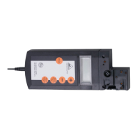
Details the function of green LEDs for current flow and a lighting LED for switch point status.
Identifies the buttons used for adjusting and configuring the unit's settings.
Details the procedure for setting the high-flow point, involving circulating flow and button presses.
Describes the process for setting the low-flow point after high-flow adjustment.
Explains red flashing LEDs for adjustment errors and lists possible causes and solutions.
Outlines how to adjust the switch point for fluctuating flows or faster response times.
Details the procedure to change the output from normally open to normally closed.
Explains how to electronically lock or unlock the unit to prevent unintentional settings changes.
| Product Name | efector 300 |
|---|---|
| Type | SR5906 |
| Manufacturer | IFM Electronic |
| Reverse Polarity Protection | yes |
| Overvoltage Protection | yes |
| Electrical Design | PNP |
| Programming | not programmable |
| Short-Circuit Protection | Yes |
| Overload Protection | Yes |
| Operating Temperature | -25°C to +70°C |