4
3 Functions and features
The control monitor is designed for the connection of flow sensors of type SFxxxx�
It evaluates the sensor signals and indicates whether a preset flow value has been
reached�
• Output closed if medium is flowing / output open if no medium is flowing�
This applies to the unit on delivery: output = normally open� In case of need you
can change the output to normally closed (→ 8�2)� It then applies: output open
if medium is flowing�
• If the flow speed increases, the switching status changes when the switch point
is reached�
• If the flow speed falls again, the switching status changes when the value "SP
minus hysteresis" is reached�
The hysteresis is considerably influenced by the set monitoring range and
it changes with the flow velocity (the higher the flow velocity the higher the
hysteresis)�
The response time of the unit is max� 1���10 s� It can be influenced by the setting
of the switch point:
• Low switch point = quick reaction with rising flow�
• High switch point = quick reaction with falling flow�
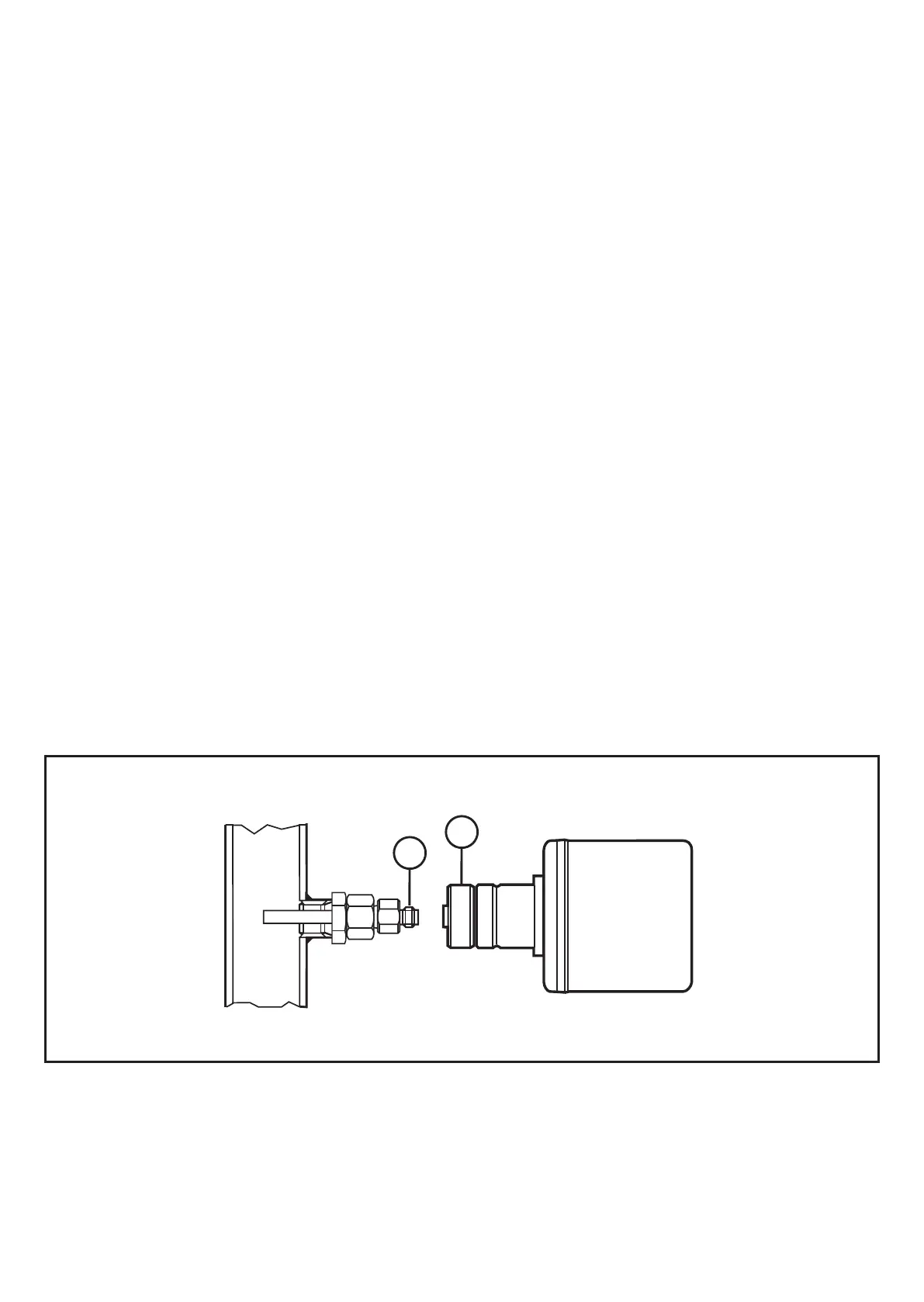
4 Installation
1
2
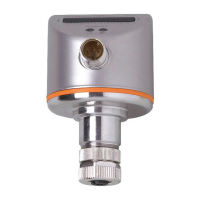
► Attach the control monitor to the flow sensor (1)�
► Tighten the coupling nut (2)�
The flow sensor must be directly connected to the control monitor� A connection by
means of extension cables is not allowed�
 Loading...