7
UK
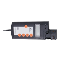
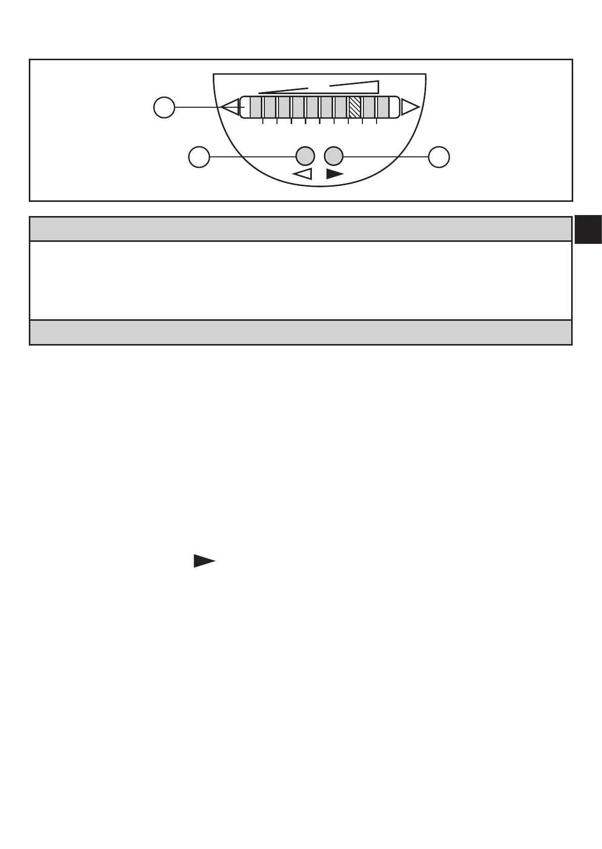
6 Operating and display elements
1: Operation display
• The green LEDs indicate the current flow (the LEDs 0 to 9 represent the range bet-
ween no flow and maximum flow)�
• A lighting LED indicates the position of the switch point (orange = output closed, red =
output open)�
2, 3: Setting buttons for adjustment and configuration
7 Set-up
For the set-up, high-flow and low-flow adjustment have to be carried out�
7.1 High-flow adjustment
► Let the normal flow circulate in the installation�
► Switch on the supply voltage�
> All LEDs light and go out again step by step� During this time the output is
closed (if configured as normally open)� The unit is in the operating mode�
► Press the pushbutton
and keep it pressed�
> LED 9 lights, after approx� 5 s it flashes�
► Release the pushbutton�
 Loading...