8
7.2 Low-flow adjustment
Note: The low-flow adjustment has to be made after the high-flow adjustment�
► Let the minimum flow circulate in the installation or ensure flow standstill�
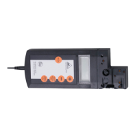
► Press the pushbutton
and keep it pressed�
> LED 0 lights, after approx� 5 s it flashes�
► Release the pushbutton� The unit adopts the new value and passes into the
operating mode�
The unit is now adapted to your flow conditions�
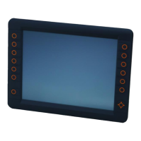
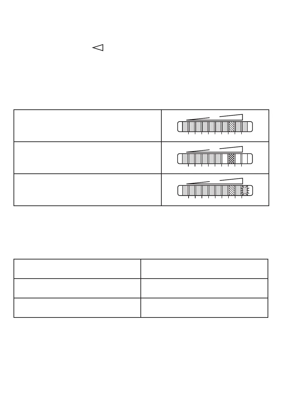
> For normal flow the display should now show example 1�
Example 1:
Unit adjusted
Example 2:
Unit not adjusted� Your normal flow is below the
representation range of the display�
Example 3:
Unit not adjusted� Your normal flow exceeds the re-
presentation range of the display (LED 9 flashes)�
7.3 Error during adjustment
If no adjustment is possible, all LEDs flash red� The unit then passes into the
operating mode with unchanged values�
Possible cause /aid:
Error during installation of the flow sensor�
► Read chapter 4�1� Check whether all
requirements have been met�
The difference between maximum flow and
minimum flow is too small�
► Increase the flow difference and carry
out the adjustment once again�
The sequence high-flow /low-flow adjust-
ment was not adhered to�
► Carry out the two adjustment operations
again in the right sequence�
 Loading...