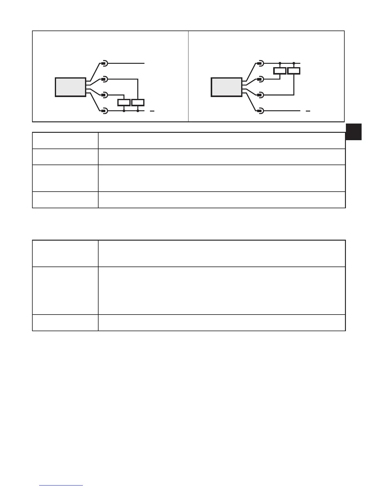
5.1 Sample circuits for connection of TR7439
2 x positive switching 2 x negative switching
L
L
+
3 BU
4 BK
2 WH
1 BN
L
L
+
3 BU
4 BK
2 WH
1 BN
Pin 1 L+
Pin 3 L-
Pin 4 (OUT1)
• Switching signal: limit values for temperature
• IO-Link
Pin 2 (OUT2) • Switching signal: limit values for temperature
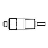
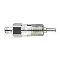
5.2 Connection for temperature sensor
2-wire sensor
Menu setting: Mmod = 4w, links between 1 / 2 and 3 / 4�
A wiring fault can be corrected in the menu COF�
3-wire sensor
Menu setting: Mmod = 3w, link between 1 / 2�
The maximum cable resistance of 10 Ω per core must not be exceeded
(this corresponds to a cable length of approx� 80 m for a wire cross-
section of 0�14 mm²)�
4-wire sensor Menu setting: Mmod = 4w�