7
UK
Enable zone for selected materials*:
Material Enable zone
FE360 (= mild steel) 0�5���4 mm
Stainless steel 0���3�1 mm
AIMg3G22 0���1�8 mm
CuZn37 0���2�0 mm
Copper 0���1�2 mm
* Typical values for damping with a reference target of 12 x 12 x 1 mm and non-flush
installation to IEC 60947-5-2 at an ambient temperature of 20 °C�
Depending on the characteristics of the damping element there may be no
close zone�
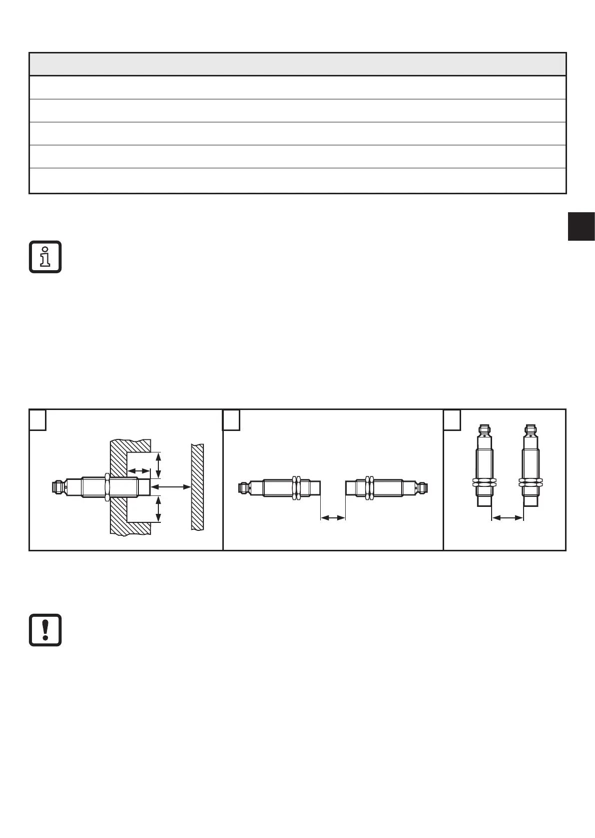
6 Installation
The unit is non-flush mountable according to IEC 60947-5-2, type I2A12SP2�
► Ensure the unit cannot work loose (tightening torque ≤ 7 Nm).
► Adhere to the installation conditions in accordance with the figures 1 to 3:
► Tighten the socket according to the manufacturer's indications� Observe the
tightening torque for the ifm socket (e�g� EVxxxx: 0�6���1�5 Nm)�
Flush installation of the fail-safe sensor is not permitted since this can result
in an increase of the sensing range up to enabling of the outputs (OSSDs)�
 Loading...