CompactModul Metall CR2032
14
CR2032 Technical data
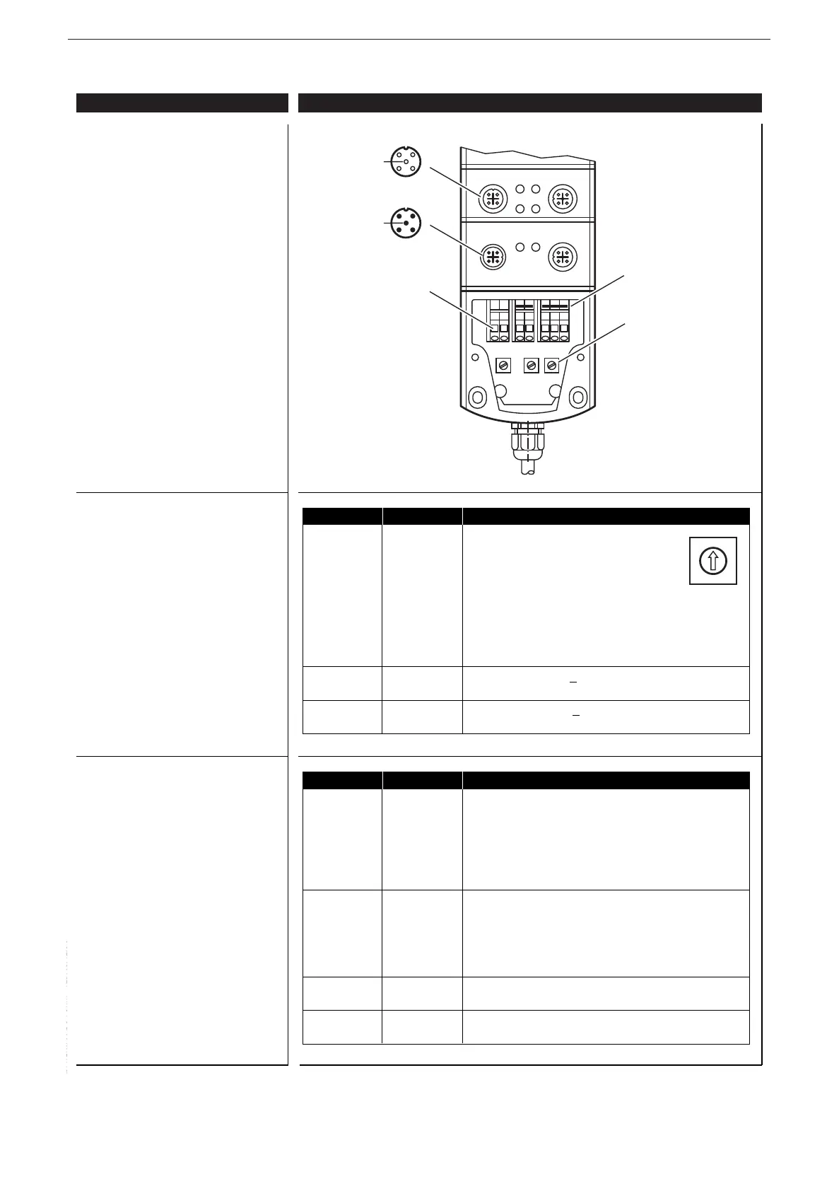
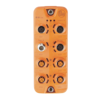
Connecting and operating elements
Hex-code switch coding
Operating states (LEDs)
Control systems
\DATEN\100\DB-FORM—PZD/03/12/96
ifm electronic gmbh • Friedrichstraße 1 • 45128 Essen
14.08.2014We reserve the right to make technical alterations without prior notice. CR2032 / page 2
LED Status Description
PWR (
green
) OFF no supply voltage
ON module in stand-by mode
CANopen status: PREOPERATIONAL / PREPARED
outputs = OFF
2.0 Hz module active
CANopen status: OPERATIONAL
outputs are updated
DIA (
red
) OFF communication OK
ON communication disturbed
• node guard / heartbeat error
(if node guarding / heartbeat is activated)
• no synch objects
(if synch monitoring is activated)
IN (
yellow
) ON binary output switched
2.0 Hz diagnosis failure
OUT (
yellow
) ON binary output: output switched (ON)
analogue output: PWM preset value ≠ 0
Switch Position Description
S1 0 1000 Kbits/s
Baud rate 1 800 Kbits/s
2 500 Kbits/s
3 250 Kbits/s
4 125 Kbits/s
5 100 Kbits/s
6 50 Kbits/s
7 20 Kbits/s
8...E not defined
F adjustment via object directory (default)
S2 0...7 high nibble, e.g. 2
0 hex (= 32 dec)
Node ID
H
F adjustment via object directory (default)
S3 0...E low nibble, e.g. 20
hex (= 32 dec)
Node ID
L
F adjustment via object directory (default)
0
•
2
•
4
•
6
•
8
•
A
•
C
•
E
•
Hex-coded
rotary switch
CAGE CLAMP
®
connection clamps
Jumper headers
upon delivery:
3+4 / 5+6+7