CompactModul Metall CR2032
6
If the M12 connectors are used for the device supply and CAN connection, close
the terminal chamber with the supplied M16 cover plug (remove the cable gland
and insert the M16 cover plug)�
6.4 Definition of short-circuit and overload protection
● Short-circuit test:
All outputs must withstand a short-circuit current limited to 60 A flowing be-
tween output and ground (GND) or supply voltage (+V
BB
)�
Test duration: 3 minutes
● Overload test:
Outputs must not be destroyed by a 100 % overload�
(e�g� nominal switching current IN = 2 A ® 100 % overload = 4 A)
Test duration: 5 minutes
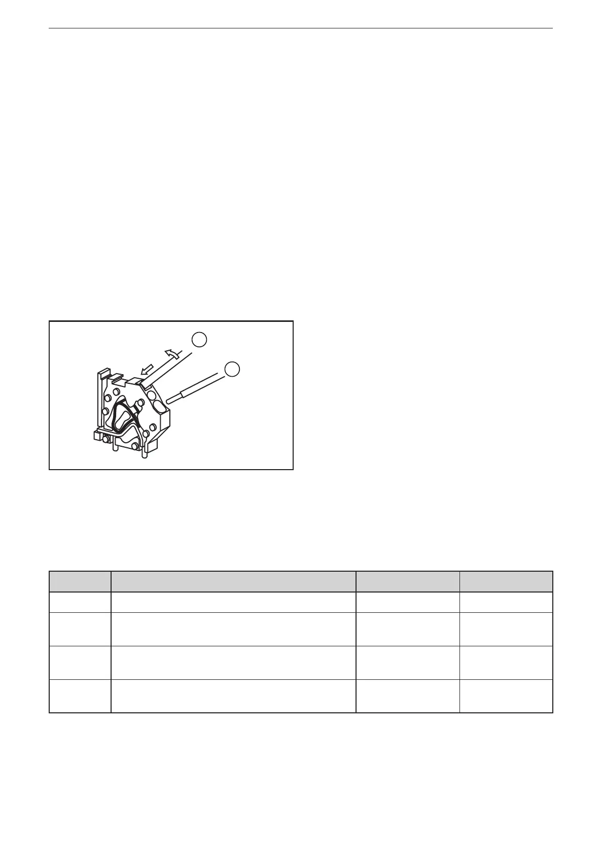
6.5 CAGE CLAMP ® connection technology
1
2
1: Screw driver
2: Wire
► Insert screw driver and tilt slightly�
> spring opens
► Insert wire�
► Remove screw driver�
> spring closes
6.6 Fuses
To protect the whole system (wiring and module) the individual electric circuits are
to be protected using fuses according to the type of connection and jumper set-
tings� The M12 plugs are designed for max� 4 A, the clamps for max� 16 A�
Example Connection (→ 6.7) Jumpers Fuse
1 Supply via M12 CANin/CANout plug 3+4 / 5+6+7 4A
2 Supply via clamps
(not via M12 CANin/CANout plug)
3+4 / 5+6 16A
3 Separate supply via clamps
and M12 CANin/CANout plug
6+7 16A
4A
4 Supply via clamps
(via M12 CANin/CANout plug)
6+7 16A
4A