CabinetModule CR2016
16
CR2016 Technical data
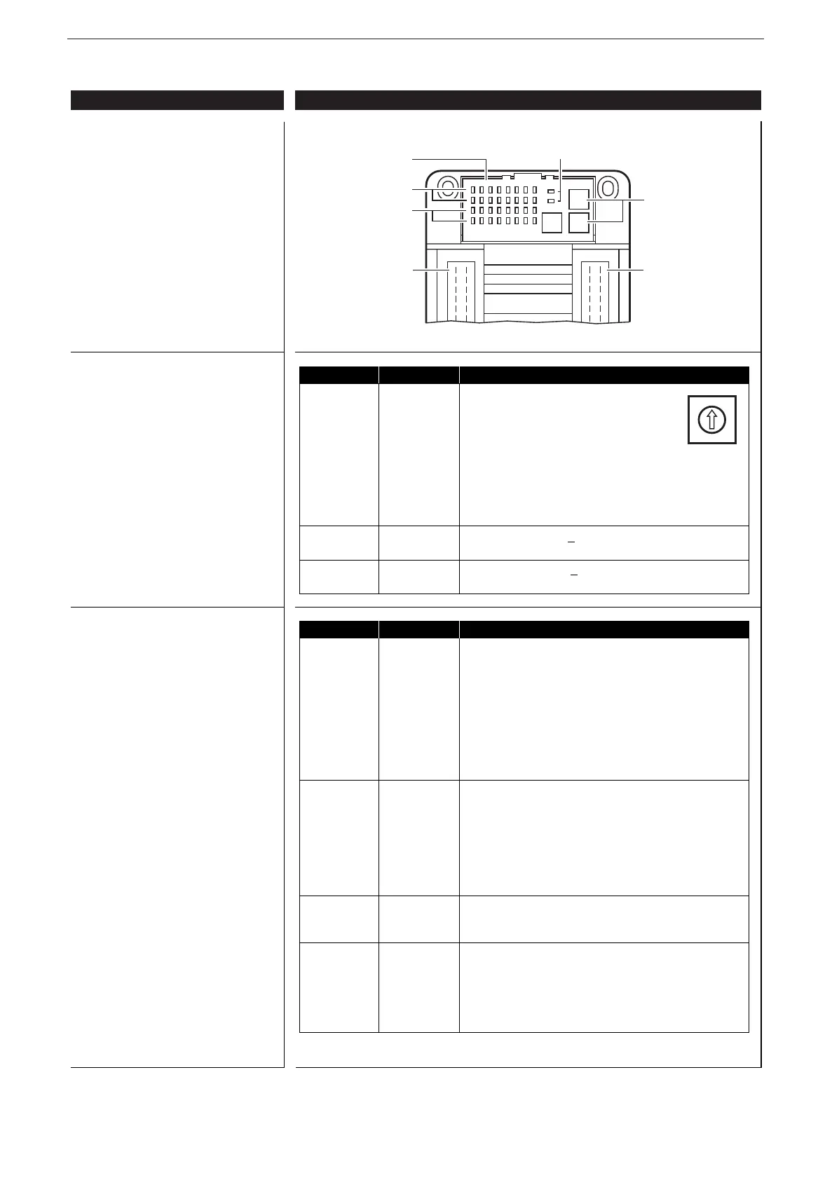
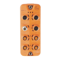
Operating and indicating elements
Rotary switch coding
Operating states (LEDs)
ifm electronic gmbh • Friedrichstraße 1 • 45128 Essen
01.10.2015We reserve the right to make technical alterations without prior notice! CR2016 / page 2
LED State Description
PWR (green) OFF no supply voltage
ON module in stand-by mode
CANopen status: PREOPERATIONAL
outputs = OFF
1 x ON module in stop mode
CANopen status: STOP
outputs = OFF
2.5 Hz module active
CANopen status: OPERATIONAL
outputs are updated
DIA (red) OFF communication OK
ON communication disturbed, CAN bus OFF
1 x ON communication disturbed
• CAN error warning level exceeded
2 x ON • node guard / heartbeat error
(if node guarding / heartbeat is activated)
3 x ON • no synch objects
(if synch monitoring is activated)
IN (yellow) OFF input not switched
LED 1...16 ON input switched
2.0 Hz
analogue input in current mode has excessive current
OUT (yellow) OFF binary output not switched (OFF)
LED 17...32 analogue output:
PWM preset value < 1% measuring range
ON binary output switched (ON)
analogue output:
PWM preset value > 2% measuring range
Switch Position Description
S1 0 1000 Kbits/s
Baud rate 1 800 Kbits/s
2 500 Kbits/s
3 250 Kbits/s
4 125 Kbits/s
5 100 Kbits/s
6 50 Kbits/s
7 20 Kbits/s
8...E not defined
F adjustment via object directory (default)
S2 0...7 high nibble, e.g. 2
0 hex (= 32 dec)
Node ID
H
F adjustment via object directory (default)
S3 0...F low nibble, e.g. 20
hex (= 32 dec)
Node ID
L
F adjustment via object directory (default)
0
•
2
•
4
•
6
•
8
•
A
•
C
•
E
•
Rotary switch
(hex-coded)
AMP
Crimp connector
outputs
LEDs 1...16 IN
LEDs 17...32 OUT
Transparent cover
AMP
Crimp connector
inputs
LEDs PWR/DIA