14
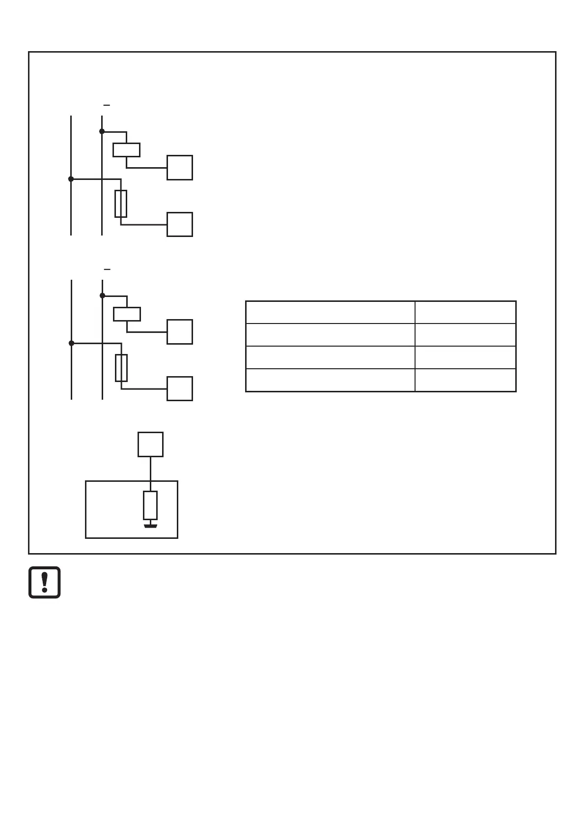
7.7 Output circuit
Connect the load
12
K1
3,6 A
22
L
L
+
24
K2
3,6 A
23
L
L
+
► Connect the load to be controlled to the relay
outputs 23/24 or 12/22�
For the output circuit, the G2001S uses two guided
contact safety relays�
► Protect the output contacts with a slow-acting
3,6 A fuse�
Check if the loads correspond to the values in the
table below�
Min� voltage > 18 V DC
Min� current > 20 mA
Max� voltage < 250 V AC
Max� current < 2 A
21
Input
SPS
The auxiliary output (terminal 21) provides a non
safety-related signal for communication to a PLC�
The signal corresponds to the relay outputs 23/24
or 12/22�
Check the proper function of the entire safety system (safety relay and
safety light curtains / light grids) after electrical connection�
► Interrupt the protected area of the safety light curtain / light grid
> Relay outputs of the G2001S drop out
→ 5.1.3 LED states (GUARD/BREAK)