7
UK
5 Structure and operating principle
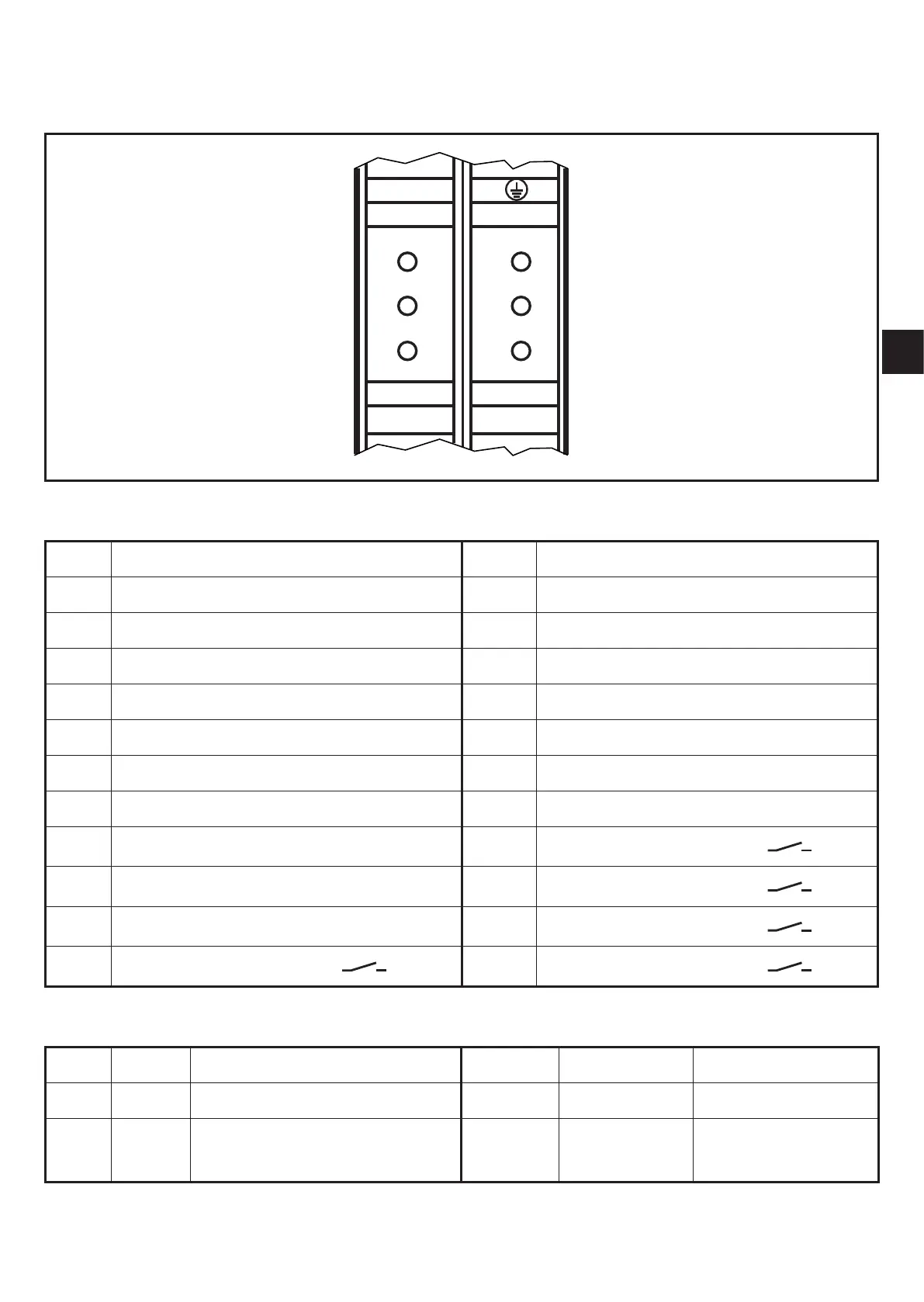
5.1 Connections and indicators
1
4
7
10
8
11
9
12
19
22
20
23
21
24
5 6 16 17 18
2 3 13 15
S1
S2
MUT.
IN
FAIL
GUARD
BREAK
5.1.1 Connections
1 Muting sensor S1 13 Supply voltage L-
2 Muting sensor S2 14 PE (GND)
3 Supply voltage L+ 15 Restart
4 Timeout 1 16 n� c�
5 Timeout 2 17 Input OSSD 1
6 Operating mode MAN/AUTO 18 Input OSSD 2
7 Override 1 19 n� c�
8 Override 2 20 Feedback contact K1/K2
9 n� c� 21 Auxiliary output
10 Muting lamp 22 Relay output R2
11 Muting activation 23 Relay output R1
12 Relay output R2 24 Relay output R1
5.1.2 LED displays
S1 yellow status muting sensor S1 IN green status OSSDs
S2 yellow status muting sensor S2 FAIL red failure
MUT� yellow muting status
GUARD
BREAK
green / red /
yellow
status relay output
R1/R2