9
UK
6 Installation
Mount the unit on a DIN rail in a housing protected against dust and humidity (min�
IP 54 - degree of soiling 2)�
Leave enough space between the unit and the top and bottom of the housing to
enable air circulation and to avoid excessive heating�
Take into account the internal heating of all units when mounting several units side
by side� The environmental conditions must be observed for every unit�
7 Electrical connection
► Disconnect power� Also disconnect any independently supplied relay load
circuits�
Note: Lay the safety relay cables separately from sources of interference
such as power lines�
Connection cables between safety relay and safety light curtains /light grids of a
length of more than 50 m must have a cross-section of min� 1 mm²�
The safety relay is only to be used for muting applications in conjunction
with safety light curtains / light grids�
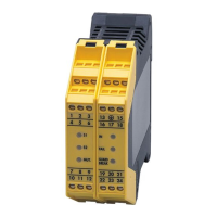
7.1 Supply voltage
The nominal voltage is 24 V DC� This voltage may vary between 19�2 V and
28�8 V incl� 5% residual ripple� SELV /PELV power supplies are to be used�
Connect supply voltage
L
L
+
13
3
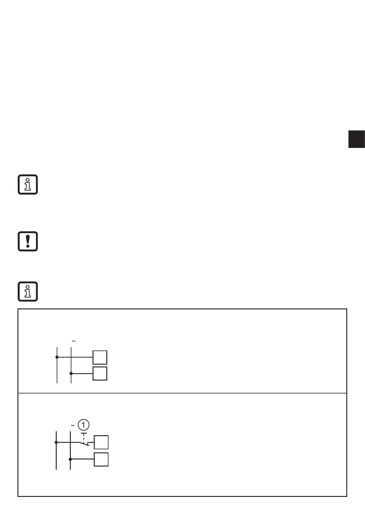
Manual reset
L
L
+
3
13
For safety reasons the unit can only be restarted by
separation from the supply voltage in case of a fault�
It is thus recommended to install a reset button in
series with the L+ circuit�
1: Reset