10
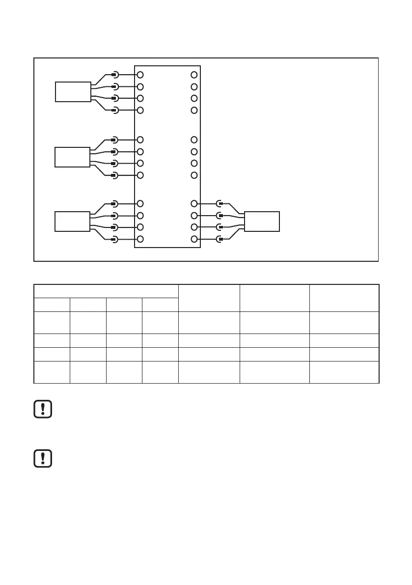
7.1 Wiring
18
17
20
19
14
13
16
15
22
21
24
23
6
5
8
7
2
1
4
3
10
9
12
11
Supply L- (GND)
OU 1: switch/analog
OU 2: switch
IN 1 (0/4...20 mA / pulse)
GND 1
IN 2 (0/4...20 mA / pulse)
GND 2
1
2
3
4
4
3
2
1
1
2
3
4
1
2
3
4
Supply L+ (24 V DC ±20 %)
Sensor 1
Sensor 2
Sensor 3
Sensor 4
Wiring of 1���4 (S1���S4) according to the use of the sensors
Sensor VSA IEPE/VSP 0���20 mA
S1 S2 S3 S4
09 16 20 24 BN: L+ (+ 9 V) not connected
(n�c�)
not connected
(n�c�)
10 15 19 23 WH: signal IEPE + signal
11 14 18 22 BU: GND IEPE - GND
12 13 17 21 BK: test not connected
(n�c�)
not connected
(n�c�)
Terminal 1 supply L+
When using an IEPE input 24 V DC + 20% (Integrated Electronics Piezo
Electric)
The ground GND of the DC supply is directly connected to the ground GND
of the sensor supply� Therefore the SELV criteria have to be met for the DC
supply�
► Protect the supply voltage externally (max� 2 A)�
7.2 Connection of the sensors
Adhere to the SELV criteria (safety extra-low voltage, circuit electrically isolated
from other circuits, ungrounded) when the sensors are connected so that no
dangerous contact voltages are applied to the sensor or transferred to the device�
 Loading...