UK
7
Firmware and operating software → download area www.ifm.com
A description of all firmware parameters and their meaning → VES004 PC
software manual�
5.2 Functional overview
With the device
– vibration monitoring (total vibration to ISO)
– condition monitoring (condition-based monitoring on the basis of vibration
characteristics)
– machine protection/process monitoring (monitoring vibration characteristics
in real time with a very fast response time up to 1 ms)
can be implemented�
Monitoring of
– up to 24 objects (indicators for different machine parts, vibration
characteristics or process values)
– dynamic values within the time range (e�g� v-RMS to ISO)
– dynamic values within the frequency range FFT or HFFT (e�g� imbalance or
rolling element bearing)
– process values (analogue signals) for current value above or below the limit
The device has an internal history memory (600,000 values) with real-time clock
and flexible memory interval per object� The memory is a ring memory (FIFO)�
Up to 32 counters can be configured to measure the duration of exceeding the
limit and/or operating times�
The signals at the inputs are permanently picked up and continuously monitored
according to the set parameters�
With objects within the frequency range (imbalance, rolling element bearing ���) the
multiplex mode is used for monitoring�
With objects within the time range (v-RMS, a-RMS and a-Peak) all 4 dynamic
inputs are monitored simultaneously and without interruption�
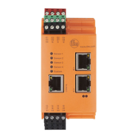
The two outputs OU1/2 can be used for alarms� The respective object states per
sensor are also indicated via the 4 sensor LEDs�
The system LED displays the operating status of the device�
Parameter setting of the monitoring tasks and alarming is effected by the VES004
software� The software allows to display and record the current measured values,
spectra and time signals (online data)�
Via the Ethernet interface of the device, networking is possible to visualise data
(measured values, alarm states, ���) in other systems (e�g� SCADA, MES, ����)�