8
Data (e�g� measured values, alarm states, limits, rotational speeds, timer readings,
���) is exchanged between the diagnostic electronics and the Modbus TCP client/
master (e�g� PLC)�
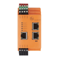
6 Installation
► Mount the unit in a control cabinet with a protection rating of at least IP 54 to
ensure protection against accidental contact with dangerous contact voltages
and against atmospheric influence�
The control cabinet should be installed in accordance with local and national rules
and regulations�
► Mount the unit vertically on a DIN rail�
► Leave enough distance to neighbouring heat sources and between the unit and
the top or bottom of the control cabinet to enable air circulation and to avoid
excessive heating�
► Prevent the penetration of conductive or other dirt during installation and wiring�
When preparing for cable installation, the local conditions and the corresponding
mounting regulations are very important� Cables can be installed, for example, in
cable ducts or on cable bridges�
Data corruption and loss
A minimum distance between the cabling and possible sources of
interference (e�g�, machines, welding equipment, power lines) is defined
in the applicable regulations and standards� During system planning and
installation, these regulations and standards must be taken into account
and observed�
Protect the bus cables from sources of electric/magnetic interference and
mechanical strain�
Observe the following guidelines regarding "electromagnetic compatibility"
(EMC) to keep mechanical risks and interference to a minimum�
6.1 Sources of interference
Signal cables and power supply lines should not be installed in parallel�
► If necessary, metal isolating segments should be placed between the power
supply lines and signal cables�
► During installation, all connector locking mechanisms (screws, coupling nuts)
must be firmly tightened in order to ensure the best possible contact between
shielding and ground� Before initial startup, the ground or shielding connection
of cables must be checked for low-resistance continuity�