OPERATION MANUAL
IFF-701Ti
1-2-2
Page 9
Jul 1/00
ITEM DESCRIPTION
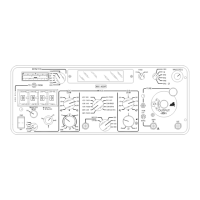
24. LOC VAR DDM/DDM SWEEP
AMPLITUDE Control
Controls variable Localizer DDM/DDM
sweep amplitude when the LOC DDM
Control is set to
↓
and according to
LOC DDM SWEEP Switch setting:
● LOC DDM SWEEP Switch set to O.
Continuously varies LOC pointer
deflection from ccw 0.4 DDM (left)
through 0 DDM to cw
0.4 DDM (right).
● LOC DDM SWEEP Switch set to
AL, S or AR.
Sets the maximum DDM
deflection/sweep amplitude from 0
to 30
µA (±0.0155 DDM) for an
automatic LOC DDM sweep.
25. 9.96 kHz REF LEVEL Control
Adjusts modulation percentage of the
9.96 kHz VAR tone (part of VOR
composite signal) from 0 to 30%. The
9.96 kHz VAR LEVEL Control (outside
larger knob) reaches 30% when
turned past 30 to the stop.
26. 30 Hz VAR LEVEL Control
Adjusts modulation percentage of the
30 Hz VAR tone (part of VOR
composite signal) from 0 to 30%. The
30 Hz VAR LEVEL Control (inside
smaller knob) reaches 30% when
turned past 30 to the stop.
ITEM DESCRIPTION
27. LOC DDM SWEEP Switch
Sets the Localizer sweep mode:
● O allows manual sweep or variable
DDM adjusted by LOC VAR
DDM/DDM SWEEP AMPLITUDE
Control.
● AR (arm right) or AL (arm left)
initializes internal sweep circuit to
0 DDM and determines initial
sweep direction prior to selecting
sweep mode (S).
● S initiates automatic LOC DDM
sweep beginning at 0 DDM and
deflecting to the direction
according to the prior arming
setting (AR or AL). The sweep
continues to the maximum pointer
deflection determined by the LOC
VAR DDM/DDM SWEEP
AMPLITUDE Control setting. The
sweep reverses and continues to
the maximum pointer deflection in
the other direction. The sweep is
symmetrical relative to 0 DDM.
28. PWR/BAT Switch
Two position switch controls power to
the Test Set:
● PWR connects Test Set to ac line
power connected to AC IN
Connector.
● BAT connects or disconnects Test
Set from internal Battery.
Connecting the Test Set to the
Battery activates an internal
battery timer. Test Set operation
disconnects from the internal
Battery after reaching the internal
battery timer limit (
≈6 to 10
minutes) or by pressing the
PWR/BAT Switch to BAT to
disconnect.

 Loading...