OPERATION MANUAL
IFF-701Ti
1-2-3
Page 1
Jul 1/00
3. GENERAL OPERATING
PROCEDURES
3.1 GENERAL
This section contains operating
instructions for the NAV-402AP. The
operating instructions contain general
procedures, identifying the controls,
connectors, indicators used for the
individual test functions. For specific Unit
Under Test (UUT) Procedures, refer to the
appropriate UUT Manual.
CAUTION: WHEN OPERATING THE
TEST SET IN A VERTICAL
POSITION, REMOVE THE
LID TO PREVENT THE TEST
SET FROM TIPPING OVER.
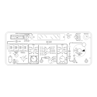
Refer to 1-2-2, Figure 2 for location of
controls, connectors and indicators.
3.2 SIGNALS SIMULATED
The NAV-402AP is a bench and ramp test
instrument for MARKER, VOR, ILS and
COM equipment.
The NAV-402AP simulates MARKER
signals with Inner (3000 Hz), Middle
(1300 Hz) and Outer (400 Hz) tones.
VOR Ground Station signals are simulated
by an RF signal modulated by a 30 Hz
reference signal, a variable 30 Hz signal
and a 9960 Hz signal.
Localizer (LOC) signals are simulated by
modulating RF with 90 and 150 Hz tones.
Glide Slope (G/S) signals are simulated
by modulating RF with 90 and 150 Hz
tones.
COM signals are simulated by modulating
RF with the 400, 1300 or 3000 Hz
MARKER tones or the 1020 Hz IDENT
tone. IDENT can also be applied to
MARKER, VOR or Localizer signals.
3.3 OPERATION CAUTIONS
The NAV-402AP must be used in the
following frequency fixed modes during
ramp use:
● COM
● G/S
● LOC
● VOR
3.4 RAMP OPERATION
With the exception of Marker Beacon,
most NAV COM systems of a typical
avionics package can be checked when
the Test Set is placed in a vertical
position in the cockpit. The antenna is
extended vertically 2-3 ft. With the
antenna on the RF Output Connector, the
VOR, LOC and G/S modes of NAV COM
Receivers can be checked and indicators
operated through the limits. The COM
Receiver can also be operated,
modulating the Test Set with either the
400, 1300 or 300 Hz tones or the 1020 Hz
IDENT tone.
On some installations, the Marker Antenna
is located far aft on the fuselage. When
this occurs, and receiver sensitivity is low
(-35 to -45 dBm), the Test Set situated in
the cockpit radiates RF insufficient to
operate the Receiver. Moving the Test
Set outside the aircraft normally provides
more than enough signal strength to
completely check Marker audio and lights.
To check COM Transmitter frequencies
from the cockpit, connect the COM
Transmitter output to the COM Transmitter
Input Connector and select MHz on the
COUNTER MODE Switch. The Test Set
reads out the COM Transmitter frequency
when the COM Transmitter is keyed.

 Loading...