OPERATION MANUAL
IFF-701Ti
1-2-3
Page 5
Jul 1/00
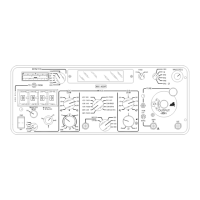
3.11 LOCALIZER OPERATION
(TYPICAL CONTROL SETTINGS)
STEP PROCEDURE
1. MONITOR METER FUNCTION
Switch
RF to verify proper leveling of
internal Signal Generator on the
MONITOR Meter.
30% to verify or set 20% modulation
of each modulating tone and set
course centering on the MONITOR
Meter.
2. COUNTER MODE Switch
GEN to read out the Signal
Generator frequency on the DIGITAL
Display when operating in fixed
(FIXED) or variable (VAR) modes.
3. FREQUENCY MODE Switch
LOC FIXED is mandatory in ramp
operation and is used on bench for a
fixed channel center frequency.
LOC VAR to check all channel bench
operation. Set VAR FREQ Controls
to select the desired channel in
25 kHz steps.
4. TUNE Control
Adjust until TUNE Indicator stops
illuminating, indicating Signal
Generator is in the fine tune range.
5. FINE TUNE switch
Press and adjust TUNE Control until
MONITOR Meter indicates least
deflection from left.
STEP PROCEDURE
6. OUTPUT ATTENUATOR Control
Use as needed to establish Receiver
sensitivities.
7. RF OUT Connector
Connect to Receiver Antenna
Connector, or attach Antenna in
ramp operation.
8. TONE SELECT Switch
Select audio tone: 1020 (Ident
tone), 400, 1300 or 3000 Hz as
desired.
9. LOC DDM Control
Use steps for precise amounts of
deflection and flag tests.
10. LOC DDM/DDM SWEEP AMPLITUDE
Control
Use to check Auto-pilot Servos,
meter stickiness, etc. or to set DDM
sweep amplitude.
11. LOC DDM SWEEP Switch
Use to select initial direction of DDM
sweep.
12. MASTER MOD LEVEL Control
Set to CAL for 20% each course
tone and 30% audio tone or variable
from 3% to 35% each course tone
and 3% to 55% audio tone.
13. PWR/BAT Switch
PWR to use external ac line power
through the AC IN Connector.
BAT to initiate operation using
internal Battery power.
 Loading...