OPERATION MANUAL
IFF-701Ti
1-2-2
Page 10
Jul 1/00
ITEM DESCRIPTION
29. MASTER MOD LEVEL Control
Controls modulation level of all
modulating tones:
● CAL (detent) position (fully ccw)
fixes modulation levels of each
type of signal to normal values;
20% for LOC, 30% for VOR and
COMM, 40% for G/S and 95% for
MKR.
● Other than CAL, adjusts
modulation levels of each type of
signal from 3% to 35% for LOC,
55% for VOR and COMM, 75% for
G/S and 96% for G/S.
30. POWER ON Indicator
Illuminates when applying ac or
battery power to the Test Set.
31. VOR BRG SELECT Switches
Four thumbwheel switches select the
VOR bearing, in degrees, simulated
by the Test Set. Valid range is 0
° to
360.0
°.
32. VOR BRG TO/FROM Switch
Changes VOR bearing selected by
VOR BRG SELECT Switches to
reciprocal bearing for flag tests, etc.
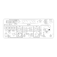
2.2 REAR PANEL
Refer to 1-2-2, Figure 2.
ITEM DESCRIPTION
33. NAV TONE OUT Connector
Provides audio output to test VOR
bearing circuits or deviation circuits of
Localizer and Glide Slope
Navigational Receivers. The MASTER
MOD LEVEL Control varies the output
level
≈0 to 7 V
P-P
into 1000 Ω. The
NAV TONE OUT Connector also
provides access to the audio
modulation of the Marker and COM
signals by connecting internally to the
Test Set Modulator.
34. SIG GEN DEMOD Connector
Provides demodulated output of the
internal Signal Generator. The
output, used for monitoring Test Set
capability, can feed VOR and ILS
Converters. If the available output
voltage is adequate and the
≈+4.25 Vdc component is acceptable,
the output can drive a Converter.
35. PWR MON DEMOD Connector
Provides access to the demodulated
output of a COM Transmitter
connected to the COM XMTR IN
Connector. The output can be used to
display modulation on an oscilloscope
or listen to modulation through an
external amplifier.
36. FUSES
Fuses input power to the Test Set.
Refer to Table 1-2-1, Table 1 for
correct fuse size and type.
37. VOLTAGE SELECT Switch
Selects 115 or 230 VAC to match
input ac power.
38. AC IN Connector
Provides input for external ac power.
Refer to 1-2-1, para 1.5 for Power
Requirements.
 Loading...