robolink
®
Joint kit – Documentation (#4; 2016-12)
igus
®
GmbH | Martin Raak | Tel. +49 (0)2203 9649 409 | mraak@igus.de 5
lock is given by 4 pcs. M4 screws in this case. Fiberglass (FGC) or carbon-fiber (CFC)
tubes can be selected as alternatives. The tube length is user selectable between l(min)
and l(max) = 1,000mm The minimum length l(min) differs depending on the location in the
system and is defined in Fig. 12 and Fig. 13. The standard length is 100 in each case.
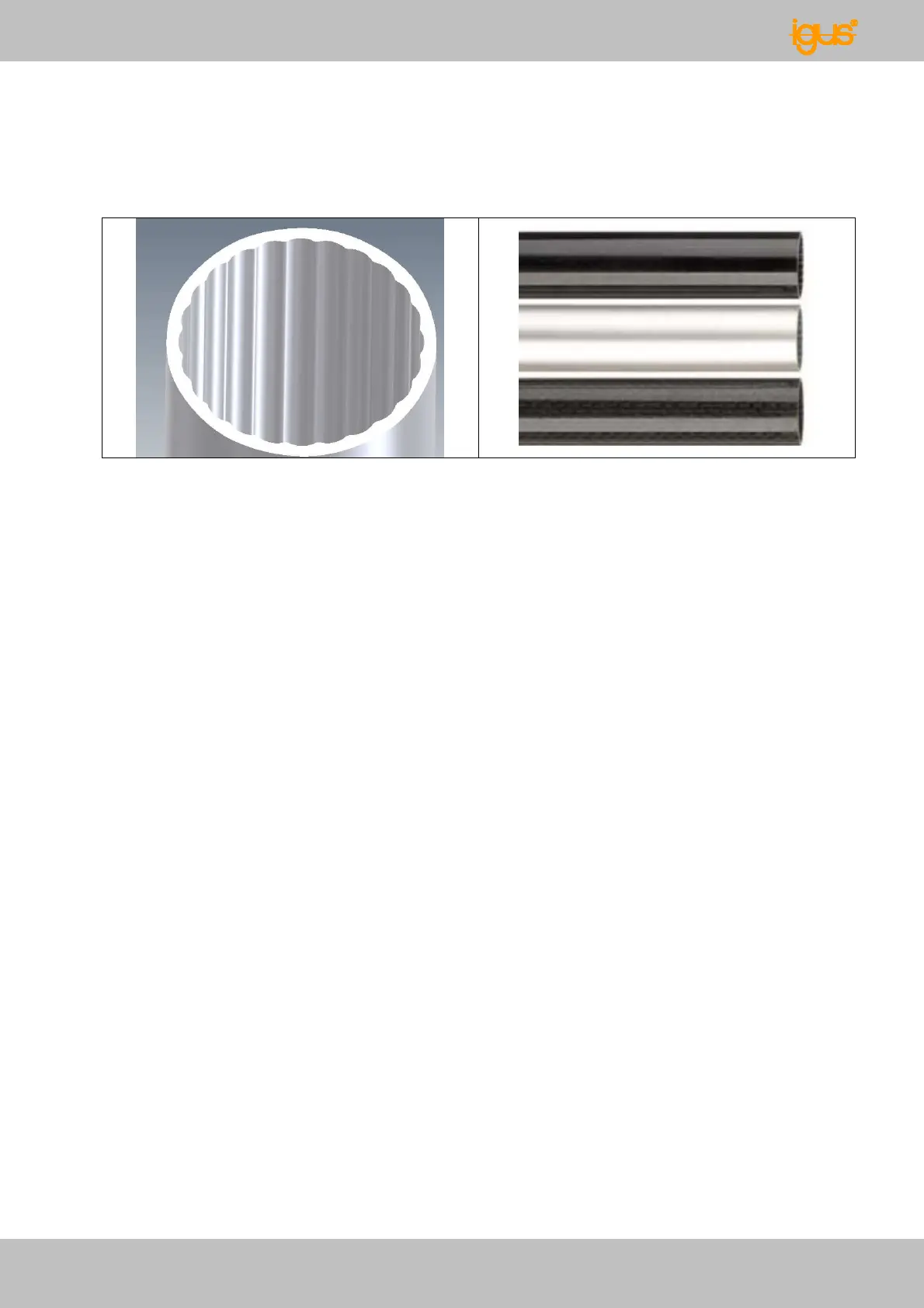
Fig. 9: Interior contour of a connecting tube Fig. 10: Material versions - connecting
tube: FGC, aluminum, CFC
The specifications for the tube lengths, visible tube lengths and rotating point distances
are shown in Figures 7 and 8, along with information for minimum lengths:
X distance of the rotating points to each other, and from the end of the arms,
Y visible tube length,
L true tube length,
1…4 the first figure is always at the beginning of the articulated arm, increasing to a
max. of 4
2 axes joints and swivel joints are designed so that a maximum of 4 wires for each joint
located above can be fed through the joint (=> Section - Draw wires). In addition, each
joint can also feed 3 more cables or hoses with a maximum diameter of 4mm.
The rotating joint can only be the first joint of a series connection, but it can feed up to 8
additional wires, and directly distribute these to the drives in wire pairs.