robolink
®
Joint kit – Documentation (#4; 2016-12)
igus
®
GmbH | Martin Raak | Tel. +49 (0)2203 9649 409 | mraak@igus.de 4
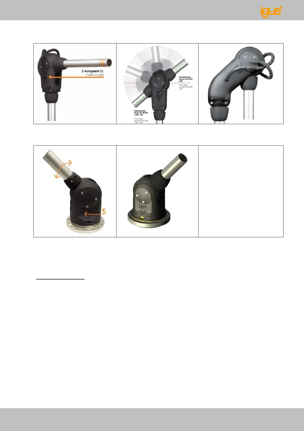
Fig.4: symmetric 2 axes
joint RL-50-001
Fig.5: asymmetric 2 axes
joint RL-50-002
Fig.6: fully swing in 2 axes
joint RL-50-003
Fig.7: Big base joint
RL-90-BL1 (2 axes)
Fig.8: Small base joint
RL-50-BL2 (2 axes)
Articulated arms
The 10 joint types can be used to configure customized articulated arms. Please consider
the following characteristics:
• Rotating joint RL-50-TL1 and base joints RL-90-BL1 and RL-50-BL2 can only be
used as first joints in a multi axes joint arm.
• Rotating joint RL-50-TL2 can only be used in annexation to base joint RL-90-BL1
(“shoulder” kinematics: rotation – pivot – rotation).
• A 6 DOF configuration needs a big base joint RL-90-BL1 as first joint.
• The small base joint RL-50-BL2 is designed for easy humanoid applications with
low additional loads (max. 5 DOF: shoulder and elbow).
• Further joint variants or higher angle range on request.
Standard aluminum tubes (dia = 26 mm) are used as connecting elements between the
joints. The tubes have an inside contour to prevent rotation on the joint interface. The big
base joint RL-90-BL1 is connected by a plain aluminum tube (da = 40 mm), the distorsion