IHP.us.com
900861-00NC
22
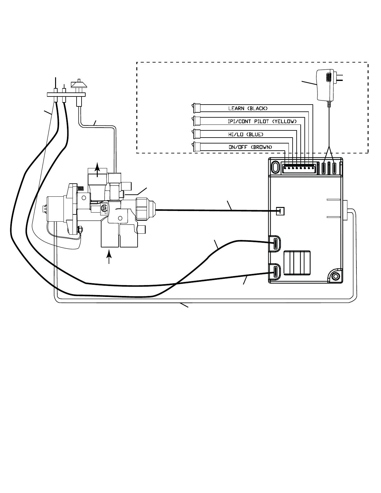
Figure 29 - This wiring diagram shows the components inside the valve box. The dotted line box shows the components external of
the valve box.
LED LIGHTING INSTALLATION
Continued
VALVE SAFETY WIRE
(V-Wire)
CAT. NO. F3482
ADAPTOR PLUGS INTO
WEATHERPROOF BOX
VCS-ECOMOD
(Control Module)
1/2 PSI
SPAIN
INLET
OUTLET
PILOT TUBE
S
I
SWITCHES
POWER
MOTOR COMM.
BATT
V
BRONZE INSULATED WIRE
BLACK WIRE
BRASS WIRE
(GROUND)
MOTOR DRIVE WIRES
TO
120VAC
POWER
SWITCHES MOUNTED
IN RGB CONTROL
ASSEMBLEY
LOW RATE
SET SCREW
These Fireplaces are equipped with an electronic gas valve and has an IPI//CPI electronic ignition system. The IPI/CPI switch allows
the pilot to be switched from intermittent mode to continuous mode:
• (IPI) Intermittent Mode—The pilot is extinguished when the fireplace is OFF.
• (CPI) Continuous Mode—The pilot stays ON when the fireplace is OFF.