900861-00NC
15
IHP.us.com
This fireplace is equipped with LED lighting. Preparation for the LED lighting a must be planned before the fireplace finish materials
are installed. After the fireplace is set in its final location the LED lighting will need to be installed and tested before finishing materials are
applied. You will need to provide the following:
(1) 120VAC GFCI outlet double gang junction box with a weatherproof cover. Provides power to LED lights. Must be accessible for service.
Follow local electrical codes for installation.
A triple gang junction box with switches is provided with the fireplace. It must be installed within the framing parameters of the fireplace.
Step 1: Install the GFCI outlet double
gang junction box with a weatherproof
cover on the opposite side of the inlet
gas supply.
NOTE: This is not a requirement; how-
ever, with the gang box on the opposite
side of inlet will create more room for
LED installation.
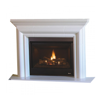
Figure 16 shows GFCI gang box in-
stalled.
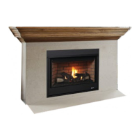
Step 2: Find mounting location for the GFCI gang box. Figure 15 shows flat area underneath burner pan. Mount box underneath the burner
pan, below the square (cutout) hole area. Figure 16 shows the GFCI outlet double gang junction box with a weatherproof cover mounted
underneath the fireplace.
Burner Pan
Support leg under fireplace
B
o
t
to
m
su
pp
o
r
t
f
i
n
GFCI Outlet installed in a double
outlet NEMA 3R enclosure
(Bring electrical up
from underneath
the fireplace)
Figure 15 - GFCI box location under fireplace
GFCI Outlet installed in a double
outlet NEMA 3R enclosure
Figure 16 - Show GFCI box mounted in fireplace
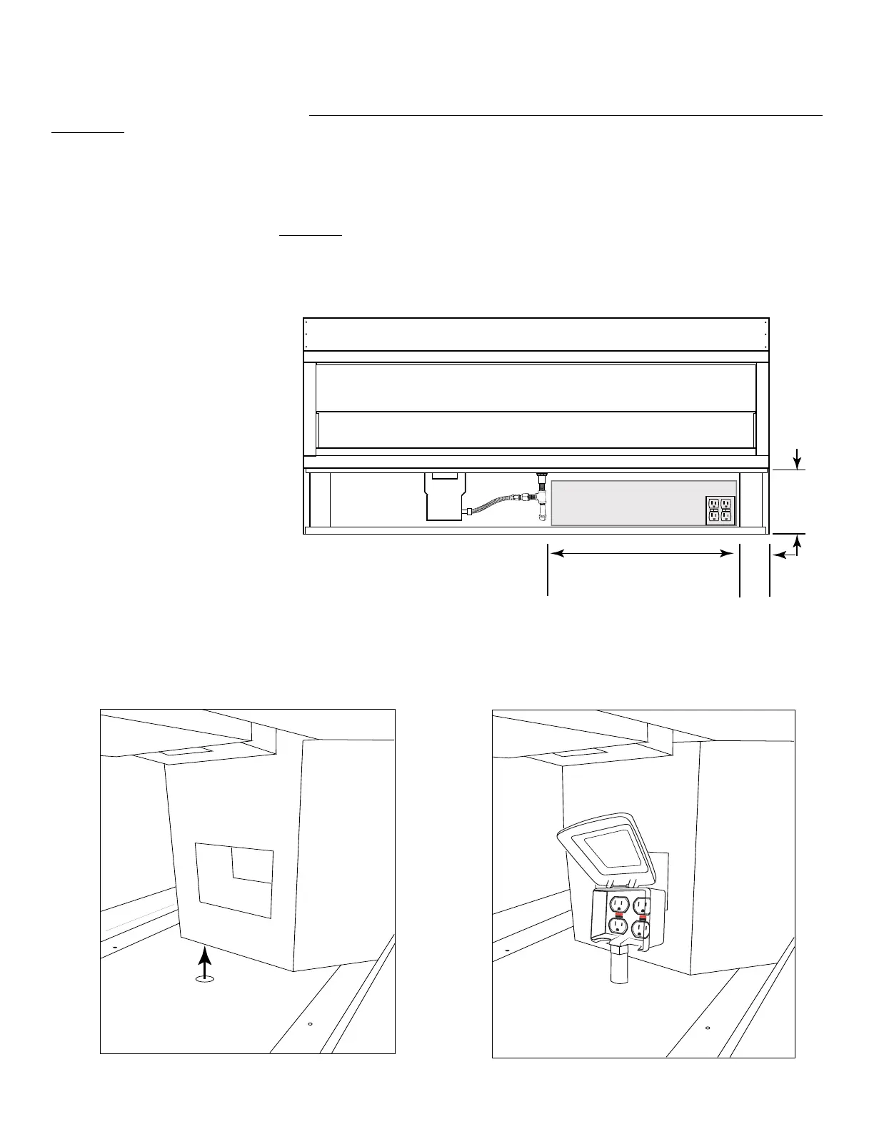
36” Model = 13” (330mm)
48“ Model = 18” (457mm)
60“ Model = 24” (610mm)
72” Model = 30” (762mm)
5”
11-1/2”
(292mm)
TYP
Electrical Area (GFCI)
The electric junction box (GFCI) with a weatherproof cover must be installed in the
shaded area shown below. Ensure the j-box is close to the floor area where the
fireplace is sitting and not touching the burner pan.
Figure 14 - Electrical Placement
LED LIGHTING INSTALLATION