12 13
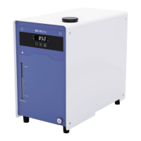
Operator panel and display
A On / Off button Switch on / off the device.
B “Set” LED The LED lights up at the same time as the set value is displayed.
C Cooling LED The light LED indicated the cooling function is activated.
D LED display
Display the settings and actual temperature values.
E “Menu” button
Press it once: menu option is display.
Press it once again: back to working screen.
F Minus (-) button
Decrease the temperature setting.
Navigation, selecting the settings in the menu.
Change the menu value setting.
G Plus (+) button
Increase the temperature setting.
Navigation, selecting the settings in the menu.
Change the menu value setting.
H “OK / Temp” button
Start / Stop the tempering function.
Confirm the menu options.
BC D
FG
H
A
E
Installation
›
Place the unit on an even, stable, clean, nonslip, dry and fireproof surface.
›
Keep at least 20 cm of open space on the front and rear side.
›
The place for installation should be large enough and provide sucient air ventilation to
ensure the room does not warm up excessively because of the heat from device radiates
to the environment.
›
Do not set up the device in the immediate vicinity of heat sources and do not expose to
sun light.
›
Cooling machine, pump motor and electronics produce intrinsic heat that is dissipated via
the venting grids! Never cover these venting grids!
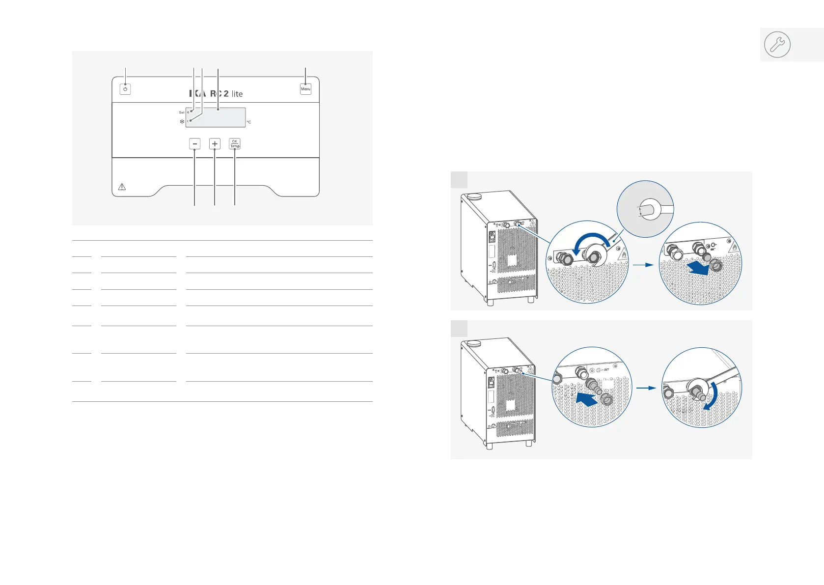
2x
2x
19 mm
2x
2x
1
2
/// Connecting the tubings and external device