3. INSTALLATION AND CONNECTION 3 - 9
BS-79 0212 VOL1 (U) (E) BS-79
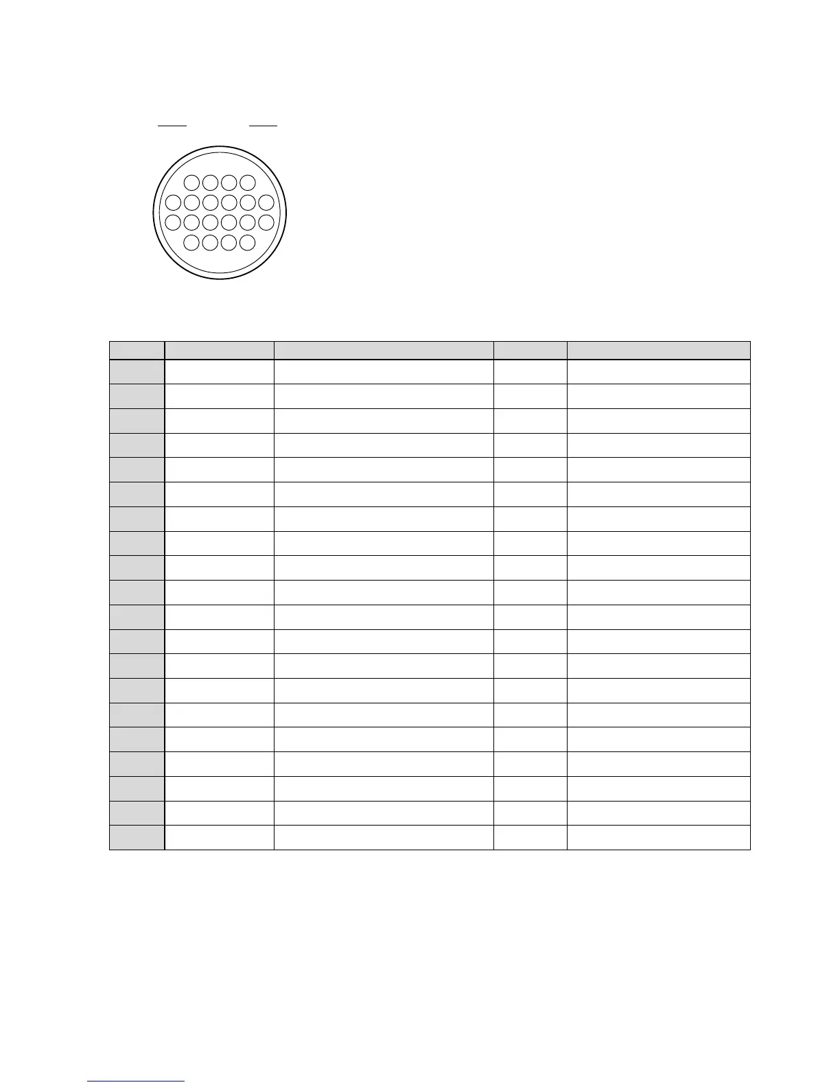
[REMOTE connector]
1
2
3
4
5
6
7
8
9
10
11
12
13
14
15
16
17
18
19
20
DATA R -> P
SP WR
SP / PS CLOCK
PS WR
DATA P -> R
BUSY
M PED (REM)
IRIS F (REM)
R BLK (REM)
G BLK (REM)
B BLK (REM)
R GAIN (REM)
G GAIN (REM)
B GAIN (REM)
REM ANS
NC
+5 V (REM)
V REF
GND
GND REF
Serial data RM → OCP/CCP
Write pulse for serial-parallel conversion
Clock output for the remote control panel
Write pulse for parallel-serial conversion
Serial data OCP/CCP → RM
BUSY signal
M PED control input
IRIS control input
R BLK control input
G BLK control input
B BLK control input
R GAIN control input
G GAIN control input
B GAIN control input
Remote answer
- - -
+5 V power output for the remote control panel
Reference voltage output for analog control
GND
GND (analog signal)
IN
OUT
OUT
OUT
OUT
IN
IN
IN
IN
IN
IN
IN
IN
IN
IN
- - -
OUT
OUT
GND
GND
This connector is used to connect a remote controller.
BS side : HR10A-13R-20SC (Hirose)
Cable side : XR10A-13P-20PC (20-pin male plug)
or equivalent
Insertion side
Pin Number
Name Function Direction External Interface
Receptacle
1
5 6 7 8 9
10
11
17 18 19 20
12 13 14 15 16
2 3 4
 Loading...