DA-6804+D
Installation and Operation Manual
9
Copyright © 2011, Harris Corporation
Jumper J3
Jumper J3 sets the control modes for all of the DA-6804+D modules (see
Figure 2-1 for the jumper location).
Installing and Removing Modules
Installation
DA-6804+D series modules cannot be installed in 6800 / 7000 series frames. See
the appropriate 6800+ series frame installation and operation manual for details
on installing and operating the frame.
Always install the back module before the
front module. Follow these steps:
1 Remo
ve the necessary number of blank back plates from the frame.
Do not discard blank back plates. They
may be needed for future
configurations.
2 Inse
rting the bottom lip of the back module into the required frame slot, and
then screw it into place.
Ensure that the EMI gaskets on the right side of t
he back module remain in
place during the installation. The EMI gaskets fit tightly.
3 In
sert the front module into the slot holding the corresponding back module.
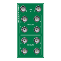
4 Attach the necessary
cables to the back module.
Removal
When removing DA-6804+D series products, always remove the front module
first.
Table 2-2 J3 Jumper Settings
Pin
Setting
Label Description
1/2 1×8_ACO Locally configures distribution amplifier as single channel (1×8) with automatic
changeover
3/4 1×8_IN1 Locally configures distribution amplifier as single
channel (1×8); input is from IN 1
5/6 1×8_IN2 Locally configures distribution amplifier as single
channel (1×8); input is from IN 2
7/8 2_1×4 Locally configures distribution amplifier as dual channel
(2-1×4)
11/12 REMOTE Enables remote control via CCS; when set to REMOTE, J3 pin
s 1-8 are not
functional