Chapter 3
Operation
12
Copyright © 2011, Harris Corporation
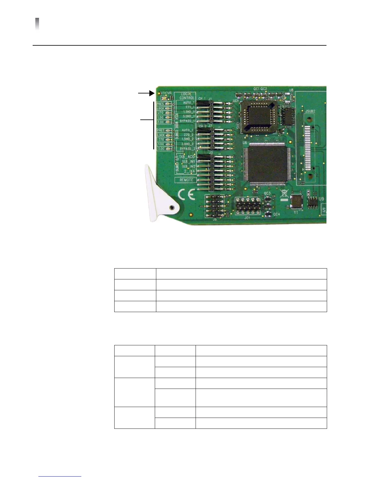
LED Displays
LEDs on the front edge of the front module report the operating status when the
power is on and signal is applied. The system status and signal condition LEDs are
shown in Figure 3-1. The individual LEDs are described on page 12.
Figure 3-1 LED Locations
Status Indicator
Signal Condition
In
dicators
Status
Indicator
Signal
Condition
Indicators
Table 3-1 Status Indicator LED Descriptions
LED Color Meaning
Off There is no power to the module;
the module is not operational.
Red The module detects an alarm condition.
Green There is power to the module; the module is operating properly.
Table 3-2 Signal Condition LED Descriptions
Name Color Function
PRES Green Input signal is present
Off Input signal is absent
LOCK Green Input signal is locked
Off Input signal is unlocked and appears on the
ou
tputs
270 Green Input signal is reclocked at 270 Mb/s
Off Input signal is not reclocked