DA-6804+D
Installation and Operation Manual
15
Copyright © 2011, Harris Corporation
Table 3-4 Remotely Controlled Parameters
Bold text = De
fault setting [RO] = Read only/feedback
Path Parameter Range Description
Processing Serial Number [RO] String Serial number for the module
License Key String License key number for the module
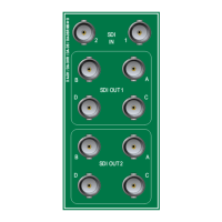
Other Output Config.
Ch.1 1×8 with ACO
Ch.1 1×8
Ch.2 1×8
2×4
Selects module output configuration
as du
al 1×4 or 1×8, 1 input routed to
all outputs; or 1×8 with input 2 routed
to all outputs
Ch.1 and Ch. 2 Signal
P
resent [RO]
No
Yes
Indicates if the input signal for the
d
esignated channel is present
Ch.1 and Ch.2 Loss of
I
nput Alarm
Disabled
Enabled
Enables or disables the Loss of Input
alar
m for the designated channel
Current Input [RO]
(valid in 1×8 with ACO
m
ode output
configuration)
N/A
Ch. 1
Ch. 2
Indicates if the input
signal is channel
1 or channel 2
Ch. 1 and Ch. 2 Slew Rate
SD
HD
Auto
Controls output/rise fall time for the
d
esignated channel
SD – Output rise/fall time complies
with SMPTE 259M
HD – Output rise/fall time complies
with SMPTE 424M /292M
Auto – Automatically selects proper
rise/fall time based on incoming
signal
Hysteresis 0.1 to 0.
5 seconds Sets the period between loss of signal
and automatic changeover; CCS is
automatically notified
Green Mode
Enabled
Disabled
Enables or disables the use of the
p
ower-saving (“green”) mode
Out 1A to Out 2D Cable
Fa
ult [RO]
Yes
No
Reports termination fault or loss of
s
ignal for the corresponding output
Ch.1 and Ch.2 Data Rate
[RO
]
Unknown
270 Mb/s
Bypass
HD
3G
Displays the locked data rate for the
d
esignated channel
Ch. 1 and Ch.2
R
e-Clocking Mode
(DA-DHR6804+D and
DA-DSR6804+D)
Auto
270 Mb/s
Bypass
HD
3G
Selects the reclock rate for the
d
esignated channel input
Ch.1 and Ch.2 Loss of
Lock Alarm
Disabled
Enabled
Enables or disables Loss of Lock alarm
on the
designated channel