7
STVkW ed 07/08 VICTRIX 24 kW Export
Technical Documentation
Technical Documentation
e hot water for heating and domestic use is produced by a
primary and secondary (D.H.W.) circuit that activated accord-
ing to the request made.
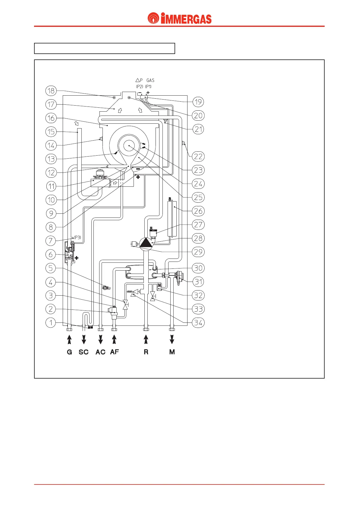
VICTRIX 24 kW hydraulic diagram.
Legend:
1 - Condensate siphon
2 - D.H.W. ow switch
3 - Flow limiter
4 - System lling valve
5 - D.H.W. probe
6 - Gas valve
7 - Gas valve outlet pressure point (P3)
8 - Venturi positive signal(P1)
9 - Venturi negative signal(P2)
10 - Venturi air/gas manifold
11 - Fan
12 - Gas nozzle
13 - Detection electrode
14 - Flue safety thermostat
15 - Air intake pipe
16 - Condensation module
17 - Draught diverter
18 - Air testing hole
19 - ∆p gas pressure point
20 - Flue testing hole
21 - Delivery probe
22 - Safety thermostat
23 - Ignition electrodes
24 - Burner
25 - Condensation module lid
26 - System expansion vessel
27 - Automatic air vent
28 - Boiler circulator
29 - System pressure switch
30 - D.H.W. exchanger
31 - 3-way valve (motorised)
32 - Automatic by-pass
33 - System draining cock
34 - 3-bar safety valve
G - Gas supply
AC - D.H.W. outlet
AF - D.W. inlet
SC - Condensation runo
R - System return
M - System delivery