2-5
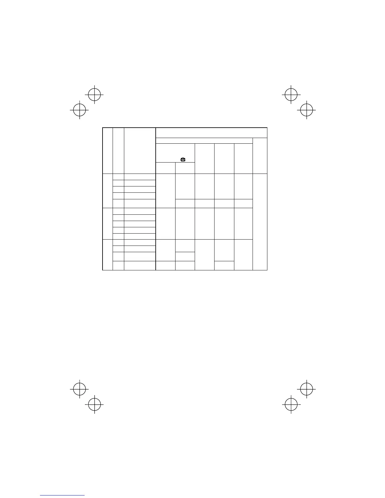
Table 2.6 Recommended Wire Sizes
*1
Recommended wire size (mm
2
)
Main circuit
Main circuit power input
[L1/R, L2/S, L3/T]
[L1/L, L2/N]
Grounding [
G]
Power supply voltage
Appli-
cable
motor
rating
(kW)
Inverter type
w/ DCR
*2
w/o DCR
Inverter
output
[U, V, W]
DCR
[P1, P (+)]
Braking
resistor
[P (+), DB]
Control
circuit
0.4
CUB3A-2
0.75
CUB5A-2
1.5
CUB8A-2
2.2
CUB11A-2
2.0 / 2.0
(2.5)
2.0 / 2.0
(2.5)
2.0 / 2.0
(2.5)
2.0 / 2.0
(2.5)
Three-phase 200 V
4.0
CUB17A-2
2.0 / 2.0
(2.5)
2.0 / 5.5
(2.5)
2.0 / 3.5
(2.5)
2.0 / 3.5
(2.5)
0.4
CUB1A5-4
0.75
CUB2A5-4
1.5
CUB3A7-4
2.2
CUB5A5-4
Three-phase 400 V
4.0
CUB9A-4
2.0 / 2.0
(2.5)
2.0 / 2.0
(2.5)
2.0 / 2.0
(2.5)
2.0 / 2.0
(2.5)
2.0 / 2.0
(2.5)
0.4
CUB3A-1
0.75
CUB5A-1
2.0 / 2.0
(2.5)
1.5
CUB8A-1
2.0 / 2.0
(2.5)
2.0 / 3.5
(4.0)
2.0 / 2.0
(2.5)
Single-phase
200 V
2.2
CUB11A-1
2.0 / 3.5
(4.0)
3.5 / 5.5
(6.0)
2.0 / 2.0
(2.5)
2.0 / 3.5
(4.0)
2.0 / 2.0
(2.5)
0.5
DCR: DC reactor
*1 Use crimp terminals covered with an insulated sheath or insulating tube. Recommended wire sizes are
for HIV/IV (PVC in the EU).
*2 Wire sizes are calculated on the basis of input RMS current under the condition that the power supply
capacity and impedance are 500 kVA and 5%, respectively.
Note 1) A box (
) in the above table replaces E suffix for filtered version.