2-7
2.3.5 Wiring for Main Circuit Terminals and Grounding Terminals
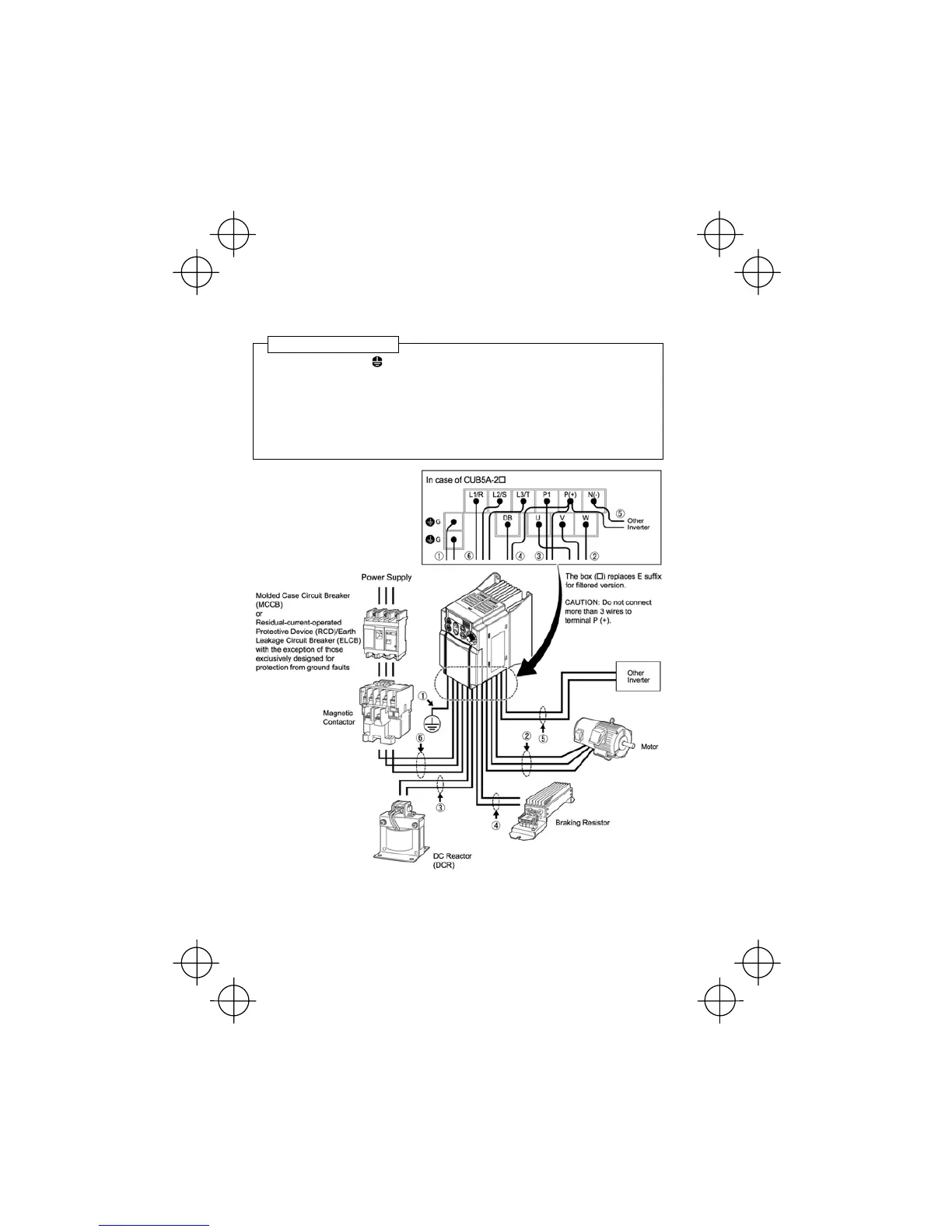
Follow the procedure below. Figure 2.3 illustrates the wiring procedure with peripheral equipment.
c Grounding terminals G
d
Inverter output terminals (U, V, and W)
e DC reactor connection terminals (P1 and P(+))
*
f Braking resistor connection terminals (P(+) and DB)
*
g DC link circuit terminals (P(+) and N(-))
*
h Main circuit power input terminals (L1/R, L2/S and L3/T) or (L1/L and L2/N)
*Perform wiring as necessary.
Figure 2.3 Wiring Procedure for Peripheral Equipment
Wiring procedure
(This figure is a virtual representation.)