3-21
Table 3.10 I/O Check Items
LED monitor
shows:
Display contents Description
4_00 I/O signals on the control
circuit terminals
Shows the ON/OFF state of the digital I/O terminals.
Refer to "
Displaying control I/O signal terminals"
below for details on the display contents.
4_01
I/O signals on the control
circuit terminals under
communication control
Shows the ON/OFF state for the digital I/O terminals
that received a command via RS485 communica-
tions. Refer to "
Displaying control I/O signal ter-
minals" below for details on the display contents.
4_02 Input voltage on terminal [12] Shows the input voltage on terminal [12] in volts (V).
4_03 Input current on terminal [C1] Shows the input current on terminal [C1] in milli-
amperes (mA).
4_04 Output voltage to analogue
meters [FMA]
Shows the output voltage on terminal [FMA] in volts
(V).
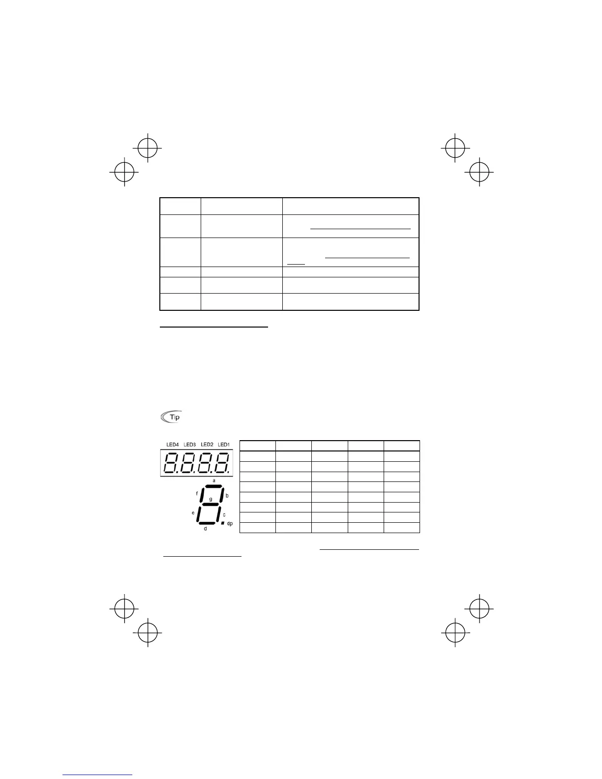
Displaying control I/O signal terminals
The status of control I/O signal terminal status may be displayed with ON/OFF of the LED segment
or in hexadecimal display.
■ Display I/O signal status with ON/OFF of the LED Segment
As shown in Table 3.11 and the figure below, segments "a" to "e" on LED1 light when the digital input
terminals ([FWD], [REV], [X1], [X2], and [X3]) are short-circuited with terminal [CM] and do not light
when they are opened. Segment "a" on LED3 lights when the circuit between output terminal [Y1]
and terminal [Y1E] is closed and does not light when the circuit is open. LED4 is for terminals [30A],
[30B], [30C]. Segment "a" on LED4 lights when the circuit between terminals [30C] and [30A] are
short-circuited (ON) and dos not light when they are opened.
• If all terminal input signals are OFF (opened), segment "g" in all LEDs 1 to 4 will blink.
• Refer to Chapter 5 "FUNCTION CODES" for details.
Table 3.11 Segment Display for External Signal Information
Segment LED4 LED3 LED2 LED1
a 30ABC Y1-Y1E — FWD-CM
b — — — REV-CM
c — — — X1-CM
d — — — X2-CM
e — — — X3-CM
f — — (XF)* —
g — — (XR)* —
dp — — (RST)* —
—
: No correlating control circuit terminals
* (XF), (XR), and (RST) are assigned for communication. Refer to "
Displaying control I/O signal terminals
under communication control" given on the next page.